PARALLAX/MAGNETEK 7345 RV CONVERTER/CHARGER REPLACEMENT
|
PARALLAX/MAGNETEK 7345 RV CONVERTER/CHARGER REPLACEMENT
|
|||||
|
REDUCE COACH BATTERY CHARGING
TIME AND ELIMINATE BATTERY OVER-CHARGING WITH RESULTANT WATER LOSS!
|
||||||||||||||||
|
|
This is a detailed procedure including 20 photos used in my 2002 Born Free 26' Rear Side Bed motor home to remove my existing single stage Parallax/Magnetek 7345 Charger/Converter section and replace it with a 3-stage Progressive Dynamics PD9160A Charger/Converter and the optional Charge Wizard. Also, Progressive Dynamics has more recently made available the equivalent PD9260C Charger/Converter that now includes the Charge Wizard function built in and is the same physical size as the PD9160A unit. NOTE: If you are removing a 6300 series charger/converter rather than the 7345 unit described in this procedure, it can be done but further instructions needed to complete the procedure properly must be complied with and are described at the very bottom of the procedure below.
|
|||||||||||||||
Parallax/Magnetek 7345 Charger/Converter conversion to 3-stage Progressive Dynamics PD9160A Charger/ConverterIn the described procedure below, the lower charger/converter section of a Parallax/Magnetek 7345 system is replaced with a 3-stage Progressive Dynamics Model PD9160A Charger/Converter along with the Charge Wizard option. Of all of the various units available from Progressive Dynamics, the PD9160A was chosen because its smaller size and dimensions fit well into the emptied lower case of the 7345 and provides sufficient space on the right end to allow good air movement for the cooling blower.
CAUTION!
TOOLS REQUIRED1) T10 Torx screwdriver 18) RECOMMENDED BUT NOT REQUIRED: DC Digital Voltmeter with at least 0.25% accuracy PARTS REQUIRED1) 15” length of black #8
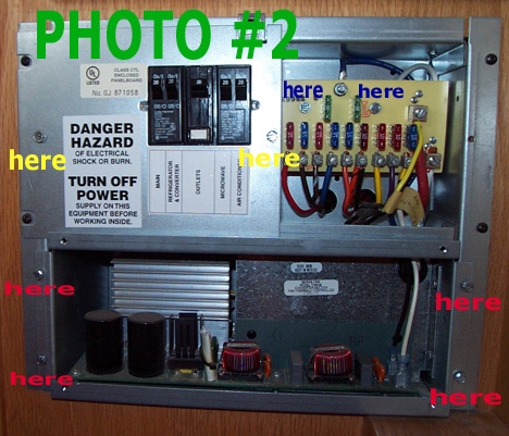
AWG battery cable MODIFICATION PROCEDURE 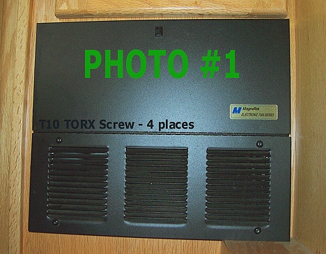 A) Reference Photo
#1
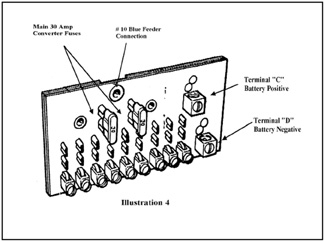
D) Reference Illustration #4
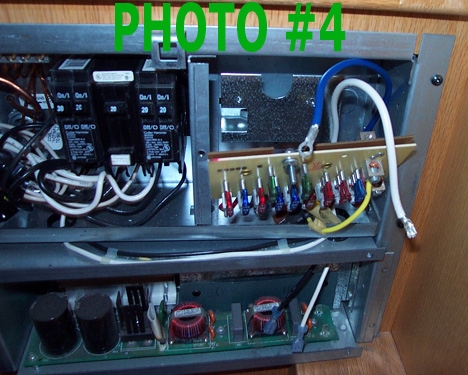
E) Reference Photo
#4
1) This photo shows these two blue and white DC wires disconnected. 2) Now unplug the black and white AC leads at their blue terminal connectors from the extreme front right side corner of the lower charger/converter section. The black #14 AWG lead is the hot side 115 VAC, 60 Hz input to the converter from either the shoreline power or the generator. The white #14 AWG lead is the neutral side 115 VAC, 60 Hz power connection. 3) Gently pull the disconnected #10 AWG white and blue DC leads down thru the black plastic grommet so that they are free from the upper section of the system. 4) Carefully pull the lower charger/converter section out of its mounting location approximately an inch or two. 5) Then gently pull the disconnected #14 AWG white and black AC leads up thru the black plastic grommet so that they are free from the lower section of the system.
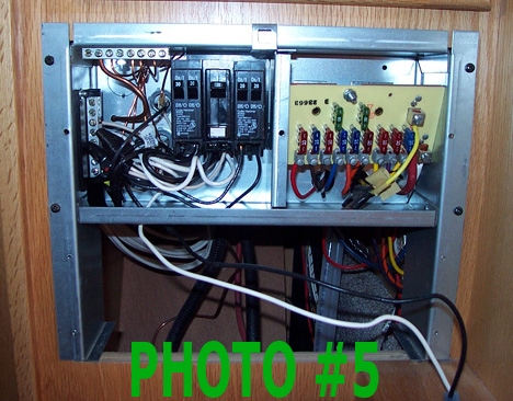
F) Reference Photo #5
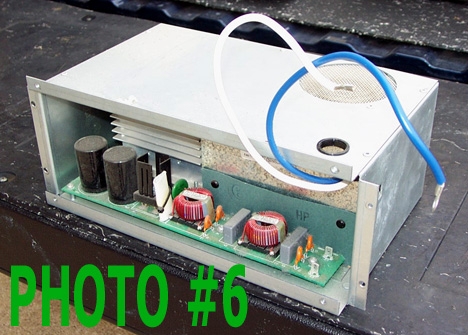
G) Reference Photo
#6
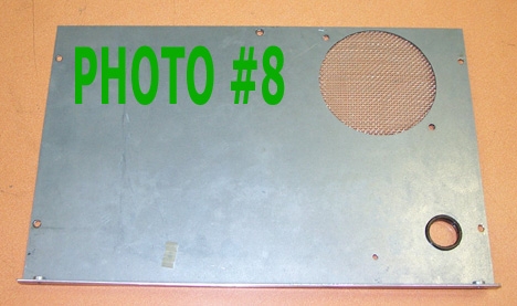
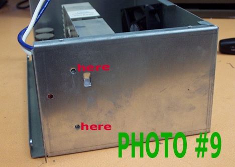
I) Reference Photo
#8
Top cover removed from main chassis and with cooling blower also unfastened is shown in Photo #8.
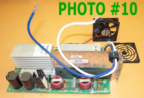
K) Reference Photo #10
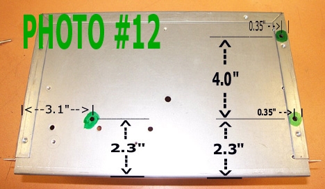
M) Reference Photo
#12
1) Photo #12 shows the bottom of the chassis with the open front of the chassis facing forward towards the bottom of the photo. 2) Mark the position of three holes to be drilled in the bottom of the chassis in the three locations as shown marked with a green felt tip pen. Carefully measure the hole locations using the dimensions shown in Photo #12. The dimensions are all from the precise edges of the chassis. 3) Once these three hole locations are correctly determined, indent the three locations with a drill punch. 4) Using a #11 drill bit, carefully drill a hole at each of these three locations. Deburr the three holes by hand with a 3/8” drill bit. 5) Using the 100 degree countersink bit, countersink these three holes from the bottom so that a #10 countersunk flat head screw will fit flush with the bottom of the case. This step is important for the case to mount and fit properly back into the system.
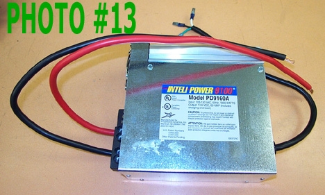
N) Reference Photo
#13
1) The new Progressive Dynamic PD9160A Charger/Converter will now be modified to install in the chassis. 2) Prepare 15” length of black #8 AWG battery cable and 17.5” length of red #8 AWG battery cable by stripping off 3/8” of insulation from both ends of both the red and black cables. 3) Insert a stripped end of the red cable into one of the two (+) terminal receptacles and tighten with 5/32” Allen wrench not to exceed 50 lb-in of torque. 4) Insert a stripped end of the black cable into one of the two (-) terminal receptacles and tighten with the allen tool not to exceed 50 lb-in of torque. 5) Take the AC power cord with 3-prong plug on the end and measure the cord from the grommet where the cord enters the chassis of the unit. Carefully measure off a 16” length of this cord from the chassis end and cut the cord at this point and discard the free end of the cord. 6) Carefully strip off 2.0” of the outer jacket insulation on the end of this cord. 7) Then carefully strip off ¼” of insulation from the white, black, and green leads protruding from this end of the cord. 8) Install and properly crimp on two ¼” wide male spade terminals on the white and black leads. These two spade terminals must be compatible with the existing two female terminals on the ends of the black and white AC power leads shown in the lower right corner of Photo #5. 9) Install and properly crimp on the blue AMP #14 AWG terminal with a #10 stud size hole in it onto the remaining green lead.
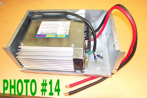
Reference Photo #14
1) In this next procedure, the Progressive Dynamic PD9160A Charger/Converter will now be mounted in the previously modified chassis. Refer to Photo #14. 2) The PD9160A has three slotted holes on its metal bottom plate. With the PD9160A inserted into the chassis firmly against the left side and back walls of the mounting chassis, insert two AN507-1032R12 (or equivalent) screws from the bottom up thru the two slotted holes on the left side of the PD9160A. Then install and tighten lightly two #10 self-locking nuts on these two screws. 3) Then insert a third AN507-1032R12 screw up thru the one remaining slotted hole on the right side of the PD9160A. Then install a #10 internally stacked lock washer on the protruding end of this screw. 4) Insert the AMP terminal on the end of the power cord green lead onto this screw on top of the lock washer. 5) Finally, install and tighten a #10 self-locking nut onto this screw with just enough torque to cause light deflection of the bottom plate of the PD9160A around the slotted hole area. 6) Then tighten the two #10 nuts on the left side with just enough torque to cause light deflection of the bottom plate of the PD9160A around the slotted hole area. 7) Dress the AC power cord above and near the rear of the PD9160A. The result should be what you see in Photo #14 above. 8) Install the Progressive Dynamics Charge Wizard P/N PD9105 by inserting the connector on the end of it's cable into the PD9160A per the factory instructions provided. 9) Coil up the excess length of the Charge Wizard cord using provided wire wraps as shown in Photo #15 so that approximately a 10" length of cord attached to Charge Wizard itself sticks out of mounting case.
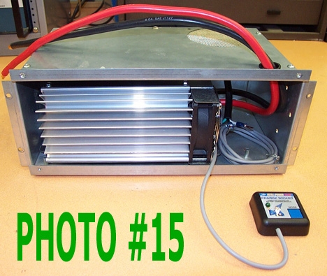
P) Reference Photo
#15
1) Install the top cover to the chassis using quantity five #6 x 3/8" Phillips head sheet metal screws 2) Even though the photo shows the red and black battery cables passing thru the plastic grommet located on the front right corner of the top cover - do not dress those cables thru that grommet hole yet at this time.
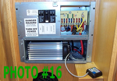
Q) Reference
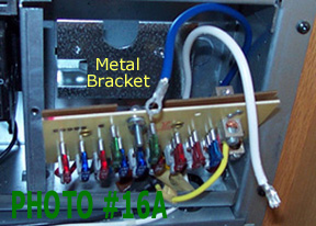
Photo #16
R) Reference Photo #16A
10)
Bend as necessary this large terminal so that it will fit and connect
properly to the #10 Blue Feeder Connection.
Then remove the #10 Blue Feeder Connection
hardware and connect the red cable terminal to the metal back plate of
this
panel. Make sure that the #10 internal stack
lock washer is placed between the red cable terminal and the metal plate
and tighten the hardware securely.
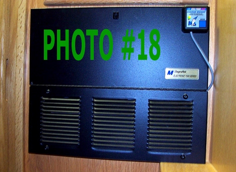
T) Reference
Photo #18 SYSTEM CHECKOUT1) Reattach (-) negative battery terminal
leads to all coach batteries. NOTE 5) In the BOOST mode with the green indicator on the Charge Wizard
showing a solid indication, the voltmeter should show +14.4 VDC. YOU ARE DONE! Prepared by: SPECIAL EXTRA PROCEDURES REQUIRED TO CHANGE
OUT A MAGNETEK/PARALLAX 6300 SERIES CHARGER/CONVERTER
1)
When removing a 6300 series charger/converter, you will find a AWG #10
blue wire was
connected to the top center terminal on the upper fuse
panel (the #10 blue Feeder Connection shown in Illustration #4
above).
A
AWG #10 red wire was connected to the upper right corner
terminal (Terminal
"C" Battery Positive) and a AWG #10 white
wire was connected to the lower right corner terminal
(Terminal "D" Battery Negative)
on the fuse panel.
2) The
blue wire previously supplied the left side 6 fused circuits
with unfiltered +12 VDC power and the red wire
previously supplied the right side 3 fused circuits with filtered +12
VDC power.
The white wire supplied the (-) neutral
connection between the fuse panel and the old charger/converter section.
3)
If the connections to this older style fuse board are left done as
instructed
above for the removed 7345 converter/charger, only the
left side 6 fused circuits will will work and the right side 3 fused
circuits will no longer have +12 VDC power to them.
4) This can be rectified by either of two methods.
Method A:
Remove the existing split circuit type fuse board assembly and
replace it with a new fuse board assembly where all 9
fused circuits are tied together. Such a new fuse board is
available
from BestConverter.com for a cost of $25.00. It
can be looked at and ordered from their website address link that
follows:
http://www.bestconverter.com/Magnetek-Fuse-Board_p_57-108.html
Remember,
if using this method, that the new fuse board must be equipped with the
two upper 30-amp fuses that the old board did not
have. The remaining fuses can be transferred from the old board to
the
new board.
Method B:
Using a red AWG #10 jumper wire, jumper together the upper center
and upper right side terminals on the existing fuse
board. This will tie together the left side 6 circuits and the
right
side 3 circuits so that the +12 VDC power coming from
the new PD9160A (or PD9160C) Charger/Converter via the red AWG #10 power
cable connected to the top center terminal on the
old style fuse panel will now power all 9 fused circuits properly.
|
||||||||||||||||