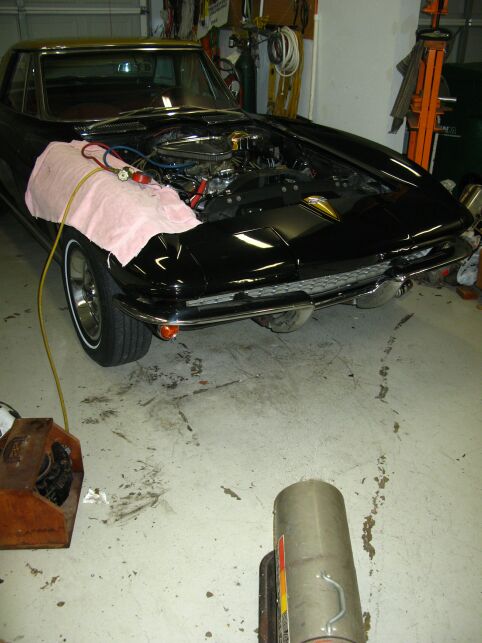
Vintage Air Install in
1967 Corvette
The
instructions say to remove the
original heater and duct work which is best accomplished by removing
the instrument panel and the glove box. Removing the instrument
panel is not REQUIRED but it does make the installation job
easier. They also
say to install the replacement defrost duct before installing the
evaporator. In my case, the evaporator was in and out several
times which succeeded in tearing the flexible hose that goes up to the
defrost duct so my recommendation would be to install the defrost duct
AFTER the evaporator is installed. See note later ... this won't
work!
Evaporator
Installation
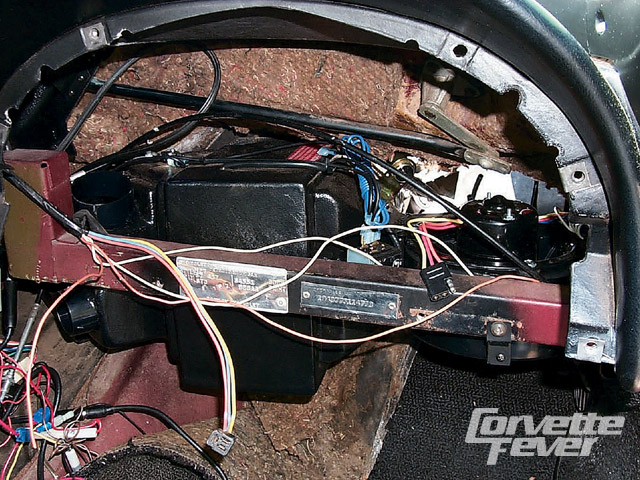
 The
installation of the unit behind the glove box is TIGHT
to say the least. The unit hangs from
one of the lower glove box mounting screws and a single hole through
the firewall that
originally held one of the anchors for the firewall insulation. In my case, the insulation had to be removed
from the
firewall behind the evaporator to have enough space to install the
unit. I tried to install the unit for a couple of hours and
finally decided that the evaporator was not the right one for this
car. I had posted some questions to the Corvette Forum and one of the
guys referred me to an article that "Corvette
Fever" did on installing Vintage Air in a mid year. They
had a LOT of VERY helpful pictures, one of which (left picture) showed
the evaporator mounted in place. That helped me realize that the
unit was NOT supposed to be level once installed and from there, I was
able to get it up into place and mounted. (right picture)
The
installation of the unit behind the glove box is TIGHT
to say the least. The unit hangs from
one of the lower glove box mounting screws and a single hole through
the firewall that
originally held one of the anchors for the firewall insulation. In my case, the insulation had to be removed
from the
firewall behind the evaporator to have enough space to install the
unit. I tried to install the unit for a couple of hours and
finally decided that the evaporator was not the right one for this
car. I had posted some questions to the Corvette Forum and one of the
guys referred me to an article that "Corvette
Fever" did on installing Vintage Air in a mid year. They
had a LOT of VERY helpful pictures, one of which (left picture) showed
the evaporator mounted in place. That helped me realize that the
unit was NOT supposed to be level once installed and from there, I was
able to get it up into place and mounted. (right picture)
Microswitch
Hits Firewall
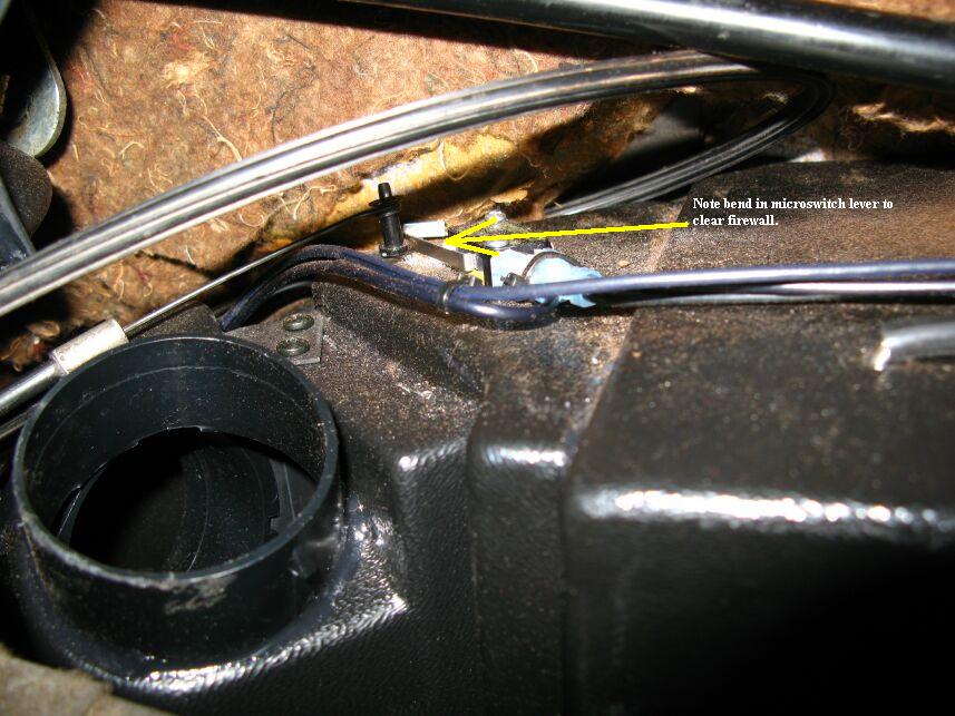 I
mentioned I had the evaporator in and out several times. One of
the major difficulties was that the AC-Heat microswitch lever ran into
the "kick-in" in the firewall that houses the wiper motor. There
was NO way the unit was going in without the switch lever being
bent. I finally pulled the evaporator back out and modified the
switch lever so it would clear the firewall and still work. In
addition, the attachment of the control cables needed some careful
"tweaking" to make sure the cables correctly activated their respective
controls.
I
mentioned I had the evaporator in and out several times. One of
the major difficulties was that the AC-Heat microswitch lever ran into
the "kick-in" in the firewall that houses the wiper motor. There
was NO way the unit was going in without the switch lever being
bent. I finally pulled the evaporator back out and modified the
switch lever so it would clear the firewall and still work. In
addition, the attachment of the control cables needed some careful
"tweaking" to make sure the cables correctly activated their respective
controls.
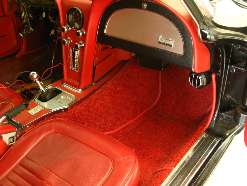
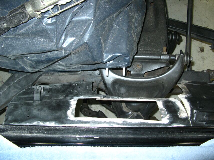
Console
Trim Won't Fit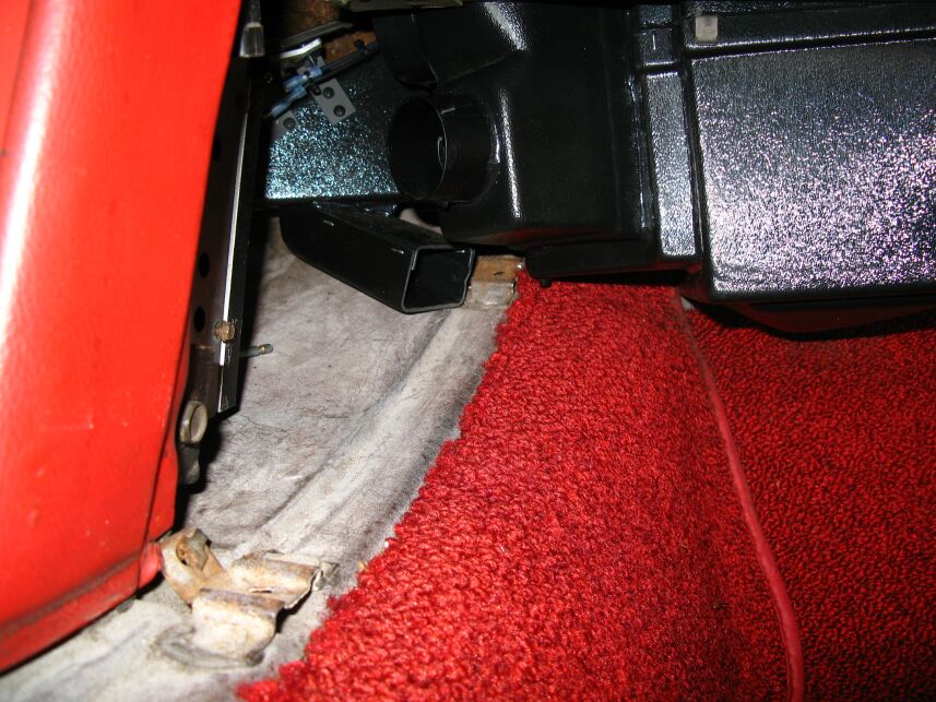
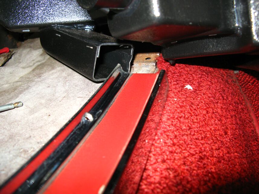
One of the most puzzling issues I ran into involved
the console trim. There was simply no way it was going to fit
back in the car. It ran very solidly into the passenger side
heater duct. I called Vintage Air and they said they always
recommend installing the evaporator with the trim in place. That
brings up a MAJOR issue in my mind because there is a screw in the trim
that would end up under the evaporator. In addition, obviously
the heater duct would end up being significantly bent up to sit on top
of that trim. Since transmission
removal (as an example) requires the removal of that trim to remove the
shifter, there would be NO way to remove the transmission with the trim
in place. VA suggested they would expect someone to remove the
evaporator to remove the trim. This was totally unacceptable to
me.
 One
of the guys on the forum said that he cut the
back off his trim to get it in place. I really didn't like the
idea of cutting a $500+ piece of trim so I started looking at
alternatives. After much thought and measurement, I used an
Exacto knife and trimmed away the offending duct just enough to get the
trim back in. I decided to do this in place which didn't result
in the prettiest cut but I wanted to make sure I trimmed in the right
place and I really didn't want to remove the evaporator again...
although by this time, I was pretty good at it. I would STRONGLY
suggest that if anyone is having a unit installed, they tell the
installer to at least remove the back screw in the trim. Then you
MIGHT be able to pull the trim out if necessary but you surely won't
get it back in without modifying the heater duct.
One
of the guys on the forum said that he cut the
back off his trim to get it in place. I really didn't like the
idea of cutting a $500+ piece of trim so I started looking at
alternatives. After much thought and measurement, I used an
Exacto knife and trimmed away the offending duct just enough to get the
trim back in. I decided to do this in place which didn't result
in the prettiest cut but I wanted to make sure I trimmed in the right
place and I really didn't want to remove the evaporator again...
although by this time, I was pretty good at it. I would STRONGLY
suggest that if anyone is having a unit installed, they tell the
installer to at least remove the back screw in the trim. Then you
MIGHT be able to pull the trim out if necessary but you surely won't
get it back in without modifying the heater duct.
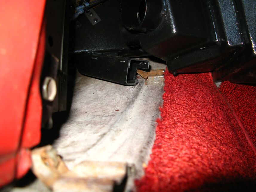
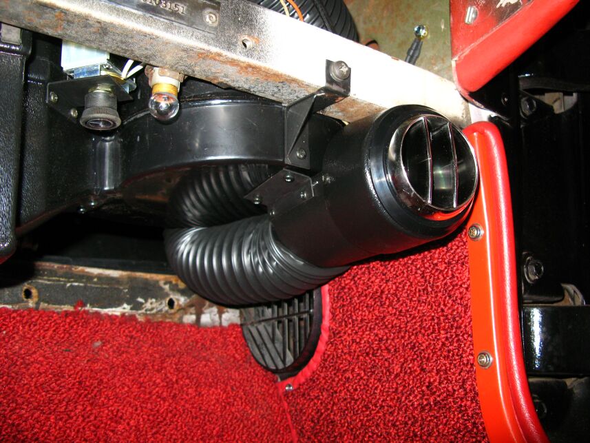
 Here's a picture of the trim
installed after cutting the duct. I did leave the trim screw
under the duct out (for obvious reasons) so the trim can be removed if
need be. Again I will say that I think Vintage Air should
STRONGLY suggest leaving this rear screw out on this side. If
someone has an installer put the unit in and that screw is left in
place, there is NO WAY
to remove the trim without removing the
evaporator box. That means you can't even replace the boot around
the shifter or the carpet without dropping the AC! That just
doesn't make sense to me.
Here's a picture of the trim
installed after cutting the duct. I did leave the trim screw
under the duct out (for obvious reasons) so the trim can be removed if
need be. Again I will say that I think Vintage Air should
STRONGLY suggest leaving this rear screw out on this side. If
someone has an installer put the unit in and that screw is left in
place, there is NO WAY
to remove the trim without removing the
evaporator box. That means you can't even replace the boot around
the shifter or the carpet without dropping the AC! That just
doesn't make sense to me.
Defroster Duct
Installation
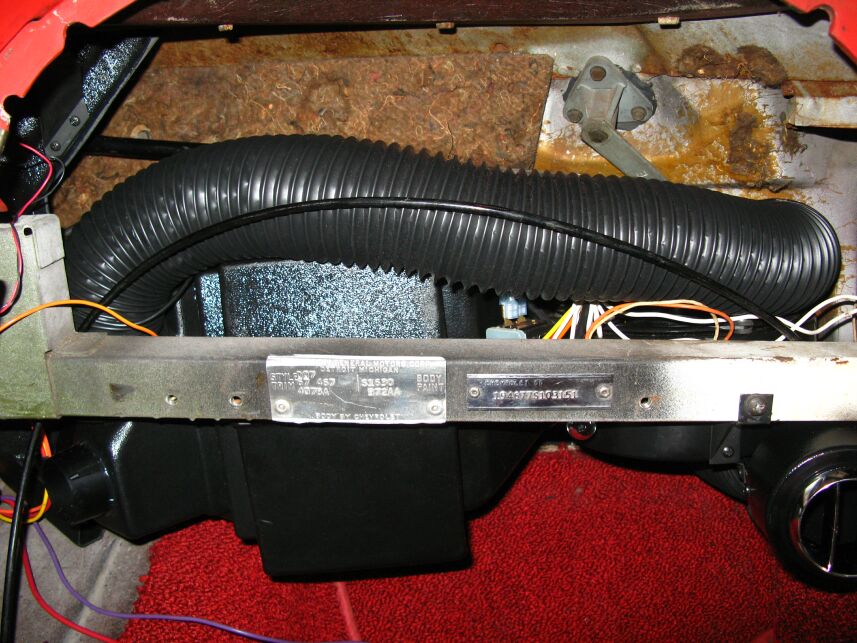
 I had originally installed the defrost
duct as the instruction manual said, before installing the
evaporator. When I installed the evaporator, the hose, which is
pre-attached to the duct got torn so I removed the duct, assuming I
could install it after the evaporator... WRONG! It wont go.
So, I dropped the evaporator again (I'm getting good at that now),
installed the duct WITHOUT the hose and then reinstalled the
evaporator, hopefully for the last time. Then I installed the
hose on the duct and secured it on both sides with a small machine
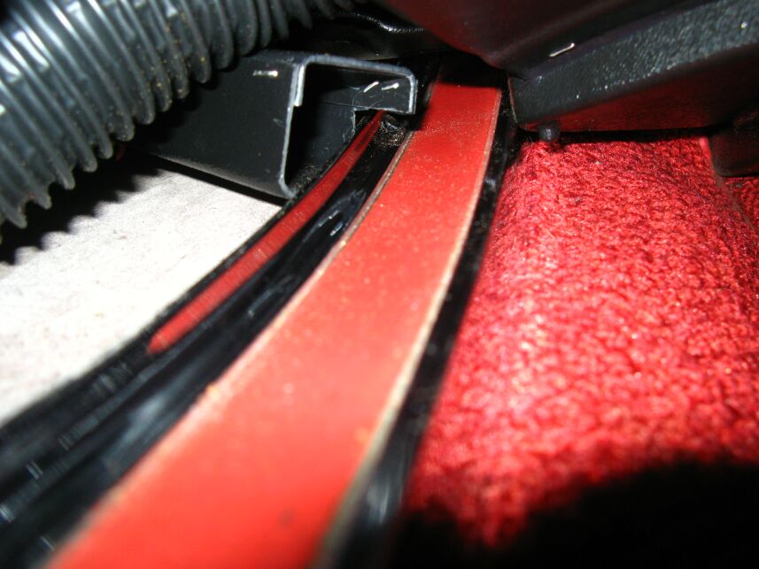
screw. In the picture you can see the first fitting of the hose
from the evaporator to the duct. The hose needed to be trimmed
slightly but after that, it fit tight but fine.
I had originally installed the defrost
duct as the instruction manual said, before installing the
evaporator. When I installed the evaporator, the hose, which is
pre-attached to the duct got torn so I removed the duct, assuming I
could install it after the evaporator... WRONG! It wont go.
So, I dropped the evaporator again (I'm getting good at that now),
installed the duct WITHOUT the hose and then reinstalled the
evaporator, hopefully for the last time. Then I installed the
hose on the duct and secured it on both sides with a small machine
screw. In the picture you can see the first fitting of the hose
from the evaporator to the duct. The hose needed to be trimmed
slightly but after that, it fit tight but fine.
 Wiring Harness,
Dash Controls & Passenger Side Air Outlet
Wiring Harness,
Dash Controls & Passenger Side Air Outlet
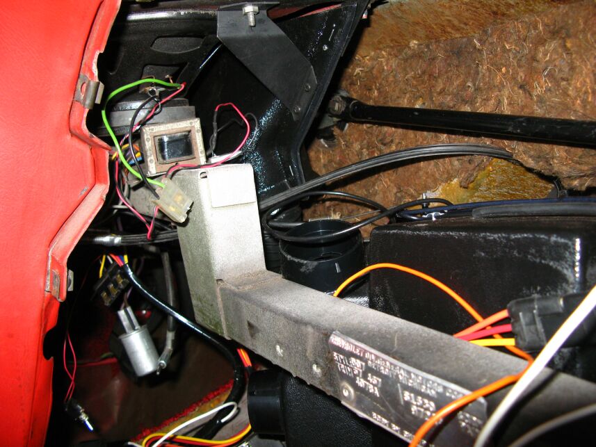
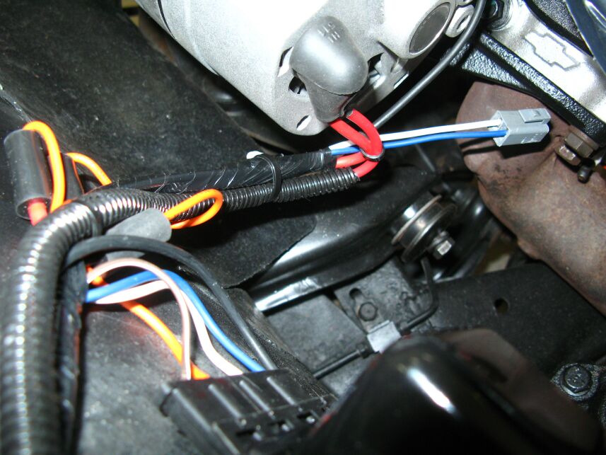
The
wiring harness was
installed next. The
instructions are not real clear so you have to read the schematic to
figure out where everything hooks up but it's not too bad. There
is one wire from the fan switch on the dash that goes to one of the
microswitches. It has a small connector on one end and a larger
one on the other with a splitter. The end with the splitter goes
to the dash switch...
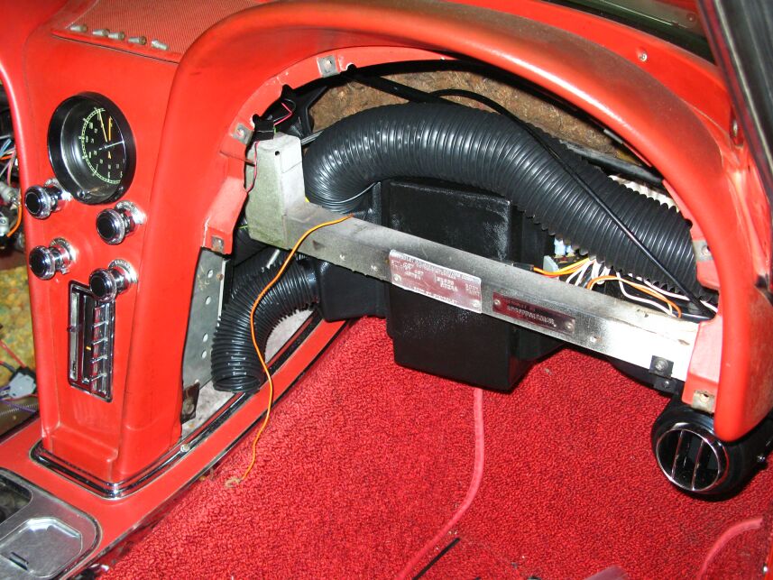
Next I installed the passenger side air
outlet. Other than the holes in the blower housing being in the
wrong place to mount the duct, it went pretty well. The hose
needs to be forced through the space between the blower and the
firewall
to get it in but it went alright. That hose was attached to the
air outlet and retained with a small machine screw as well. Then
I discovered
the air outlet covers the courtesy light. I moved the light to
the
brace,
left of the air outlet to complete that part of the job.
Vintage Air uses the factory heat controls to activate the heat and AC functions of this unit and unlike some of the competing units, there is no modification of the controls or the dash mounting holes required. After getting the evaporator and trim issues resolved, I refitted the controls to the console. Incidentally, I took this opportunity to lubricate all of the control cables with Teflon loaded silicone oil. Be very careful of the passenger side outside air (vent) control cable attachment at the vent when installing the evaporator. It is TIGHT against it and it can be easily broken. I know this for a FACT! I had to fabricate an aluminum bracket for the cable after the plastic one snapped off.
Console Side
Panels Prepared
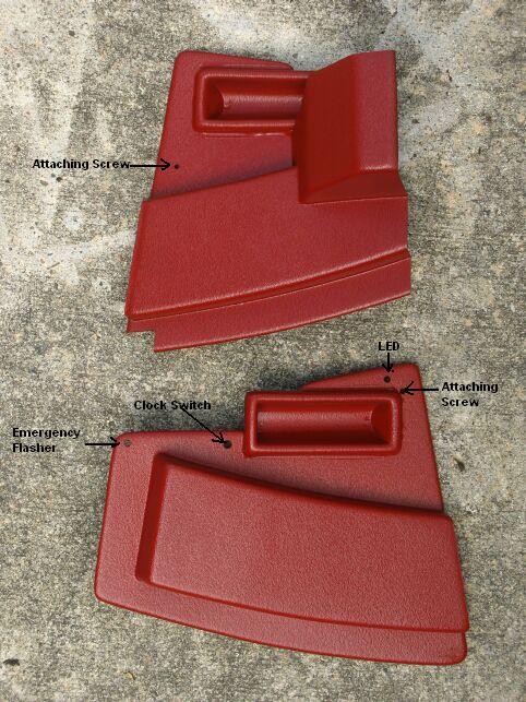
 The
right and left
console trim pieces were next. The passenger side one (top of
left picture) would NOT
fit between the console trim bracket and the vertical side of the
console so I finally decided to notch the corner of the trim and
after that, it fit very nicely. After drilling the necessary
holes for mounting and other items, the panels were painted to match
the interior and they were ready to install. The hose that
connects to this panel is VERY short as you can see in the picture on
the right but it does connect and it does work. I run a
compressor indicator LED on all of my AC systems and one of the holes
in the driver's side panel is for that. Another of the holes is
for the clock switch. Years ago, I rebuilt the clock and
installed a circuit that takes all the load off the contact points
inside so I also installed an on/off switch so I can leave the clock
off if I like. I typically turn it on only when the car is in a
show. The rear hole in the driver's panel is for the emergency
flasher that is used in the '67.
The
right and left
console trim pieces were next. The passenger side one (top of
left picture) would NOT
fit between the console trim bracket and the vertical side of the
console so I finally decided to notch the corner of the trim and
after that, it fit very nicely. After drilling the necessary
holes for mounting and other items, the panels were painted to match
the interior and they were ready to install. The hose that
connects to this panel is VERY short as you can see in the picture on
the right but it does connect and it does work. I run a
compressor indicator LED on all of my AC systems and one of the holes
in the driver's side panel is for that. Another of the holes is
for the clock switch. Years ago, I rebuilt the clock and
installed a circuit that takes all the load off the contact points
inside so I also installed an on/off switch so I can leave the clock
off if I like. I typically turn it on only when the car is in a
show. The rear hole in the driver's panel is for the emergency
flasher that is used in the '67.
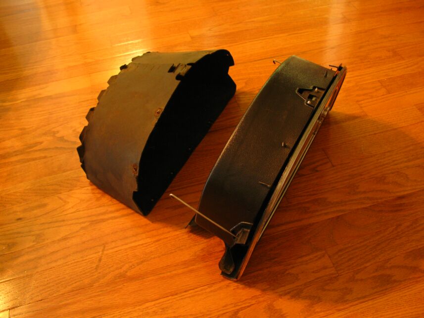
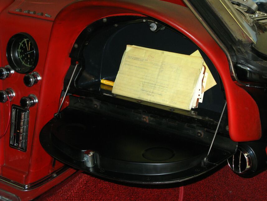
Glove Box
Modifications
 Vintage
Air doesn't address the issue of the glove
box because
it WILL go back in, in its stock form but at the expense of the right
side air duct. I put the box back in place and if bolted in, it
would crush the hose to about 50% of it's original size. In
addition, the hose would be forced up against the windshield wiper
arm. I did some research and found that Classic Auto Air has a
short glove box liner in their kit that is designed specifically to
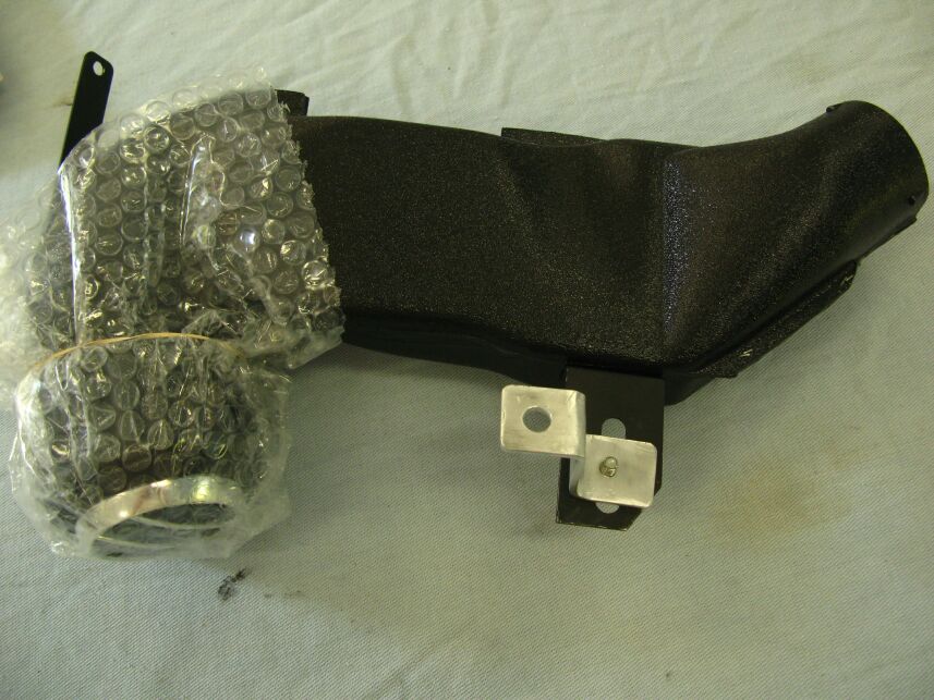
address this issue so I gave them a call. They
were happy to sell me a replacement liner for my installation.
The old box is about 6 inches deep and the new one is about 4 but I
think that's much better than giving up the air flow or damaging the
hose or wipers. You can see the difference in the picture on the
left. With the new glove box liner, I was able to install the
passenger side console vent and finish up that side. Looks pretty
good, huh?
Vintage
Air doesn't address the issue of the glove
box because
it WILL go back in, in its stock form but at the expense of the right
side air duct. I put the box back in place and if bolted in, it
would crush the hose to about 50% of it's original size. In
addition, the hose would be forced up against the windshield wiper
arm. I did some research and found that Classic Auto Air has a
short glove box liner in their kit that is designed specifically to
address this issue so I gave them a call. They
were happy to sell me a replacement liner for my installation.
The old box is about 6 inches deep and the new one is about 4 but I
think that's much better than giving up the air flow or damaging the
hose or wipers. You can see the difference in the picture on the
left. With the new glove box liner, I was able to install the
passenger side console vent and finish up that side. Looks pretty
good, huh?
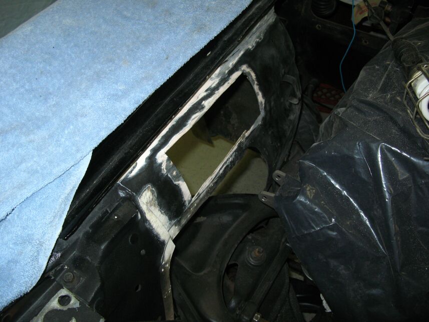
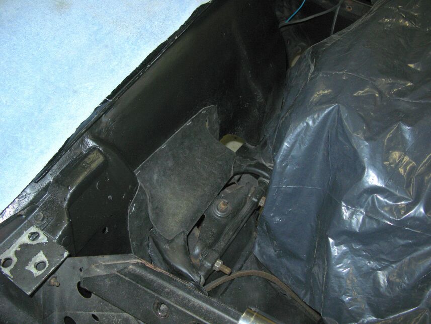
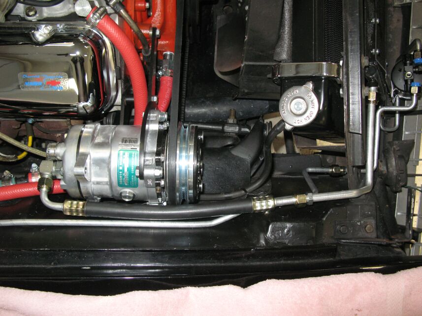
Compressor
Hits Inner Fender
Vintage Air uses compressor brackets from Alan Grove, part no.
118R. The brackets are very nicely made and accommodate cylinder
heads
with both 3/8 and 7/16 holes. Mine had one 7/16 hole so I had to
drill out one hole in the bracket for the larger bolt. Then I
tried to mount the
compressor. No chance! It ran HARD into the right inner
fender. I know the inner fender had been replaced at one time in
the life of this car but it had never been a problem before.
Well, it is now! A call to Vintage Air disclosed I DID have the
wrong compressor (mine is supposed to have the suction and discharge
ports on
the rear of the back head) but the dimensions of the compressor will be
the same so no joy, it won't fit!
While a complete new
inner fender is available
($345), I decided it was MUCH better to modify this one. After
all, I have known it had the wrong inner fender for years and it didn't
seem to make any difference in my enjoyment of the car. In fact,
I know the front end of this car has been badly damaged in the past as
evidenced by the fact that the steering column had been collapsed and
very poorly repaired before I got the car. Further evidence is
that the hood has the support on the driver's side but there was no
provision for the hood support on the driver's side and there is one on
the passenger side inner fender indicating the inner fenders must be
from a 63-65 Vette. Many years ago, I fabricated a mount for the
hood support on the driver's side inner fender.
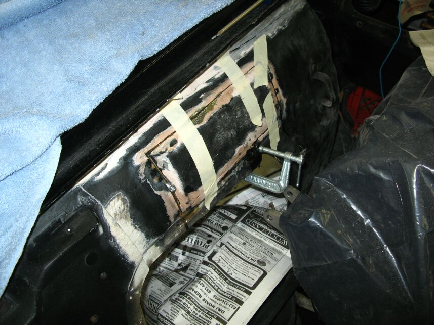 I
first
tried to cut a relief in the fender that I would have built a backing
for but the rotation of the compressor on the brackets to tighten the
belt still made it hit
the fender. With that, I got some dimensions from one of the guys
on the Corvette Forum and
then went to Corvettes of Houston and took some pictures of the
inner fender on a
small-block '67 in their showroom. It looked like my inner fender
needed to move out about 2 inches so I went to work with the saber saw
and made two vertical cuts in the inner fender. I replaced the
part
I had cut out earlier and using fiberglass mat, I reformed the contours
of the inner fender to clear the compressor.
I
first
tried to cut a relief in the fender that I would have built a backing
for but the rotation of the compressor on the brackets to tighten the
belt still made it hit
the fender. With that, I got some dimensions from one of the guys
on the Corvette Forum and
then went to Corvettes of Houston and took some pictures of the
inner fender on a
small-block '67 in their showroom. It looked like my inner fender
needed to move out about 2 inches so I went to work with the saber saw
and made two vertical cuts in the inner fender. I replaced the
part
I had cut out earlier and using fiberglass mat, I reformed the contours
of the inner fender to clear the compressor.
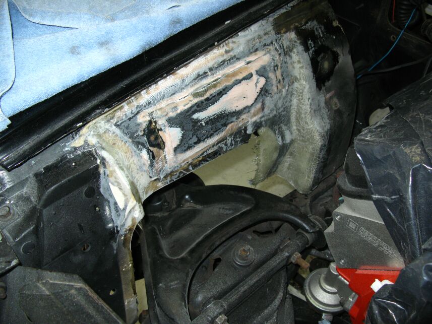
![]() I
actually ended up glassing back the first section I had cut out and
rejoined
the first vertical cut on the rear of the fender. The final fix
was a
"V" cut on either side of the splash shield. Then I swung that
section in about two inches and molded in the cut sections with
fiberglass mat
and resin. There were two unused mounting ears on the compressor
that
were pointing toward the inner fender. I removed them with a
hacksaw and
cleaned up the cuts with a file. After that, with a 59 inch belt
tight on
the compressor, the compressor clears the fender with about one inch
between
the compressor and the inner fender. To get the 59 inch belt on,
you have
to remove the adjuster bolt and swing the compressor toward the valve
cover. Then, with the belt in the groove, the adjuster bolt fits
perfectly back in the slot. I used a Gates "XL" belt from
O'Reilly's and
according to the Gates website, "...tensile cords within the XL belt
contract slightly as the belt warms to its
normal operating temperature. This feature reduces maintenance
because
once they are properly installed, Gates XL belts rarely need to be
retensioned."
I
actually ended up glassing back the first section I had cut out and
rejoined
the first vertical cut on the rear of the fender. The final fix
was a
"V" cut on either side of the splash shield. Then I swung that
section in about two inches and molded in the cut sections with
fiberglass mat
and resin. There were two unused mounting ears on the compressor
that
were pointing toward the inner fender. I removed them with a
hacksaw and
cleaned up the cuts with a file. After that, with a 59 inch belt
tight on
the compressor, the compressor clears the fender with about one inch
between
the compressor and the inner fender. To get the 59 inch belt on,
you have
to remove the adjuster bolt and swing the compressor toward the valve
cover. Then, with the belt in the groove, the adjuster bolt fits
perfectly back in the slot. I used a Gates "XL" belt from
O'Reilly's and
according to the Gates website, "...tensile cords within the XL belt
contract slightly as the belt warms to its
normal operating temperature. This feature reduces maintenance
because
once they are properly installed, Gates XL belts rarely need to be
retensioned."
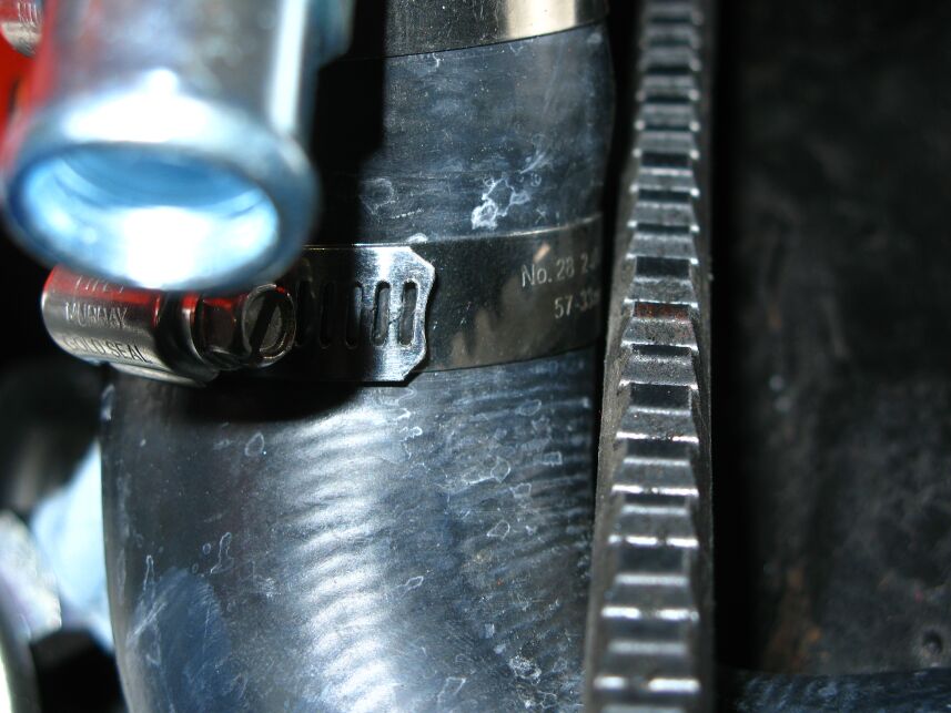
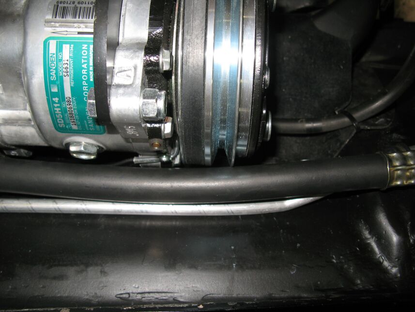
 Speaking
of clearances, the belt JUST misses the lower radiator hose where it
connects to the water pump. I put an extra stainless clamp around
the hose just in case the belt vibrates a bit. It looks closer
than it really is. There is about 1/8 inch between the belt when
it's tight and the hose. Another close place is at the top stud
for
the shock absorber. I'll cut off the shock stud a bit and slot
the remaining shaft for a screwdriver in case the shock ever needs to
be removed.
Speaking
of clearances, the belt JUST misses the lower radiator hose where it
connects to the water pump. I put an extra stainless clamp around
the hose just in case the belt vibrates a bit. It looks closer
than it really is. There is about 1/8 inch between the belt when
it's tight and the hose. Another close place is at the top stud
for
the shock absorber. I'll cut off the shock stud a bit and slot
the remaining shaft for a screwdriver in case the shock ever needs to
be removed.
Electrical
Wiring
The Vintage Air wiring harness is fed by two main wires; a red wire
that includes a 30 amp breaker and a purple wire that is supposed to go
to a line that is hot only with the key on. The purple wire only
energizes the power relay so it doesn't have to handle any appreciable
current at all. I connected that wire to the "heater" fuse in the
fuse panel. The red wire is the main wire that powers the
blower and the compressor clutch. Vintage Air says that wire is
to go directly to the battery or the battery terminal on the starter
solenoid.
That presents an interesting circumstance. The '63-67 Corvette
ammeter is actually a volt meter that is connected essentially from the
alternator to the starter solenoid. That means it is using the
wire between the alternator and the starter as a shunt and measures the
voltage drop across
it. The easiest way to explain this is if the starter solenoid
end of the shunt wire is negative with respect to the alternator end,
the ammeter will read positive and visa versa. Hooking up the red
wire to the starter solenoid means the
ammeter will NOT read the load from the blower motor with the engine
(alternator) off since it will not
create a voltage drop across the shunt. That alone is not a
significant problem but if the engine (alternator) is running, now the
current that is going to the blower motor from the alternator WILL show
on the ammeter as a charge meaning that if the battery is fully
charged, the
ammeter will be still be showing a charge, equivalent to the current
going to
the blower motor. In other words, when running the blower motor,
it will appear that the battery is ALWAYS taking current from the
alternator. Not good.
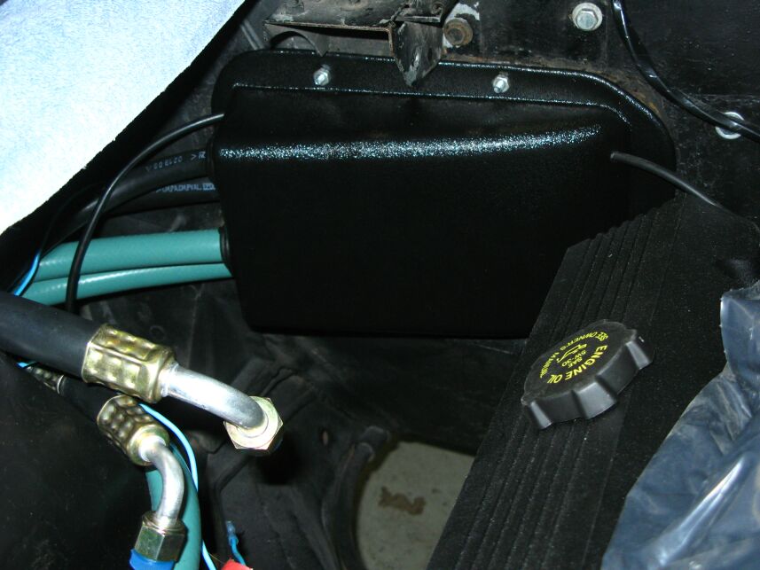
 I
decided to fix that
issue and in the process, address another known problem area in the
mid-year Corvettes. ALL the power for the inside of the car comes
through an infamous "RED WIRE" that goes through the firewall
connector. It is not uncommon to have that connector go bad from
the current draw. Since I just replaced the engine harness, I
knew the connector was clean. In addition, when I put it
together, I used dielectric grease on all the connections in the
connector to help it stay clean. I also ran another 10 ga wire
directly from the alternator to a 50 amp breaker located right next to
the voltage regulator. From that breaker, I then ran a 10 ga wire
directly through
the firewall to the "hot" side of the breaker for the headlamp
motors. That effectively puts a 50 amp supply in parallel with
the infamous red wire and the firewall connector. The
red wire from the Vintage Air was then connected to hot side of the
headlamp motor breaker, through the supplied 30 amp breaker, mounted on
the left
kick panel, next to the headlamp breaker. That should
dramatically lower the chance of failure of the firewall connection as
well as make the ammeter read correctly.
I
decided to fix that
issue and in the process, address another known problem area in the
mid-year Corvettes. ALL the power for the inside of the car comes
through an infamous "RED WIRE" that goes through the firewall
connector. It is not uncommon to have that connector go bad from
the current draw. Since I just replaced the engine harness, I
knew the connector was clean. In addition, when I put it
together, I used dielectric grease on all the connections in the
connector to help it stay clean. I also ran another 10 ga wire
directly from the alternator to a 50 amp breaker located right next to
the voltage regulator. From that breaker, I then ran a 10 ga wire
directly through
the firewall to the "hot" side of the breaker for the headlamp
motors. That effectively puts a 50 amp supply in parallel with
the infamous red wire and the firewall connector. The
red wire from the Vintage Air was then connected to hot side of the
headlamp motor breaker, through the supplied 30 amp breaker, mounted on
the left
kick panel, next to the headlamp breaker. That should
dramatically lower the chance of failure of the firewall connection as
well as make the ammeter read correctly.
Firewall Cover
and Hoses
 Vintage Air provides a nice cover that
goes on the engine side of the firewall. In fact, a casual glance
would make you think it was the factory box. There are four large
hoses that come out of the cover as well as two small vacuum hoses and
the compressor clutch wire. Two of the large hoses (black) are
the vapor return line from and the liquid line to the evaporator.
The other two large hoses are for the heater. I used Gates
silicone (green) hoses inside the box because they are lifetime hoses
and shouldn't ever need to be replaced. That's a good thing
because getting the firewall cover on (or off!) with the four hoses
through it is
a bit of a chore and I don't want to ever have to do it again.
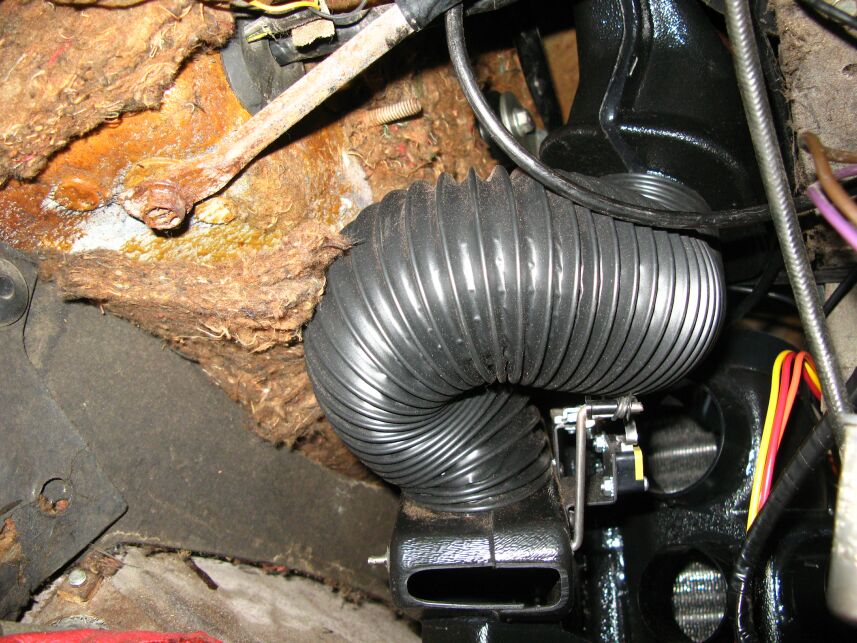
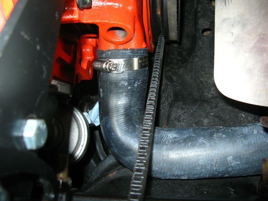
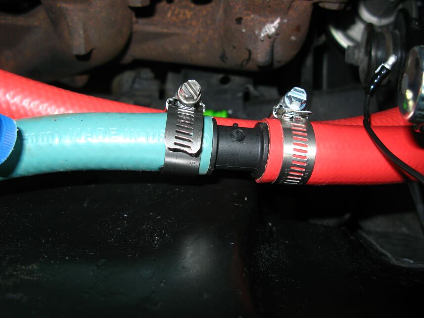
One of the heater hoses goes to the hot water control valve as does one
of the vacuum lines. The other heater hose goes to the water pump
through a 5/8 to 3/4 adapter (right pic) so I changed from silicone to
Gates red hose at the heater valve and the adapter. Incidentally,
there are special clamps that are supposed to be used with the silicone
hose. In the case of the heater hoses, it's Gates #32312.
They have an inner shield that prevents that clamp screw
from digging into the hose.
Vintage Air provides a nice cover that
goes on the engine side of the firewall. In fact, a casual glance
would make you think it was the factory box. There are four large
hoses that come out of the cover as well as two small vacuum hoses and
the compressor clutch wire. Two of the large hoses (black) are
the vapor return line from and the liquid line to the evaporator.
The other two large hoses are for the heater. I used Gates
silicone (green) hoses inside the box because they are lifetime hoses
and shouldn't ever need to be replaced. That's a good thing
because getting the firewall cover on (or off!) with the four hoses
through it is
a bit of a chore and I don't want to ever have to do it again.
One of the heater hoses goes to the hot water control valve as does one
of the vacuum lines. The other heater hose goes to the water pump
through a 5/8 to 3/4 adapter (right pic) so I changed from silicone to
Gates red hose at the heater valve and the adapter. Incidentally,
there are special clamps that are supposed to be used with the silicone
hose. In the case of the heater hoses, it's Gates #32312.
They have an inner shield that prevents that clamp screw
from digging into the hose.
As mentioned, there are
two small vacuum hoses. Vintage Air identifies them as "red and
black" although in my case, I saw no colors on the hoses and certainly
not on the ends that came through the box. . The red goes
to the water valve and the black to manifold vacuum. It's
important to
connect the correct hose to the water valve. If you suck on the
two hoses, one is blocked and one is open. The blocked one goes
to the intake manifold. If you connect the wrong one to the
intake, you will have a constant vacuum leak which might result in a
rough idle that would be LOTS of fun to figure out. Of course,
the ZZ454 is supposed to have a "nasty" idle according to Chevrolet so
I probably wouldn't have noticed it anyway but it's still good not to
have the leak.
While testing the unit,
I discovered the fan would not work all the time. After some
troubleshooting, I discovered one of the relays supplied by Vintage Air
was defective. It had a loose terminal and when wiggled, the
blower would turn on and off. A spare relay from stock fixed that
problem.
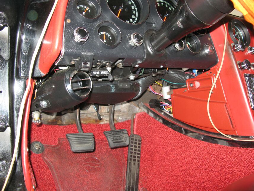 After
installing the steering column today, (11/7/09) it was time to check
the fit of the driver's side AC duct. I couldn't permanently
install it because I have to install the power booster for the brakes
yet but I can't do that until UPS delivers the valve covers from
Zip. The new covers have the recess in them to clear the power
booster. I suspected there would be a problem with the mounting
of the duct since the instructions show the mounting for an earlier
car. The '67 is the first year for the collapsible steering
column so the mounting under the dash is completely different. As
it turned out, I was able to quite nicely mount it by fabricating a "Z"
bracket that mounts off of one of the large bolts that supports the
break-away pieces of the column. Too bad that Vintage Air doesn't
at least mention this but it wasn't a big deal for me to make the
bracket.
After
installing the steering column today, (11/7/09) it was time to check
the fit of the driver's side AC duct. I couldn't permanently
install it because I have to install the power booster for the brakes
yet but I can't do that until UPS delivers the valve covers from
Zip. The new covers have the recess in them to clear the power
booster. I suspected there would be a problem with the mounting
of the duct since the instructions show the mounting for an earlier
car. The '67 is the first year for the collapsible steering
column so the mounting under the dash is completely different. As
it turned out, I was able to quite nicely mount it by fabricating a "Z"
bracket that mounts off of one of the large bolts that supports the
break-away pieces of the column. Too bad that Vintage Air doesn't
at least mention this but it wasn't a big deal for me to make the
bracket.
 On Wednesday the 9th of December, I took the car to
Firestone in Spring and had the front end
aligned. Since I hadn't charged the AC yet, I removed the
compressor so he could get to the "A"
frame bolts easier and hopefully, would not scar stuff up under the
hood. I had to remove the alternator once I got there so he could
get to those bolts as well. After that, I brought it home and
reinstalled the
compressor and TRIED to hook up the last of the hoses. The
discharge hose from the compressor was just a little too short. I
could have probably tied it to the liquid line but it would have put
undue strain on the hose so I called Vintage Air and it typical
fashion, they were quick to say they would send out a slightly longer
hose tomorrow.
On Wednesday the 9th of December, I took the car to
Firestone in Spring and had the front end
aligned. Since I hadn't charged the AC yet, I removed the
compressor so he could get to the "A"
frame bolts easier and hopefully, would not scar stuff up under the
hood. I had to remove the alternator once I got there so he could
get to those bolts as well. After that, I brought it home and
reinstalled the
compressor and TRIED to hook up the last of the hoses. The
discharge hose from the compressor was just a little too short. I
could have probably tied it to the liquid line but it would have put
undue strain on the hose so I called Vintage Air and it typical
fashion, they were quick to say they would send out a slightly longer
hose tomorrow.
 On Friday the 11th the new hose showed up and in no
time, I had it installed and started pumping the system down.
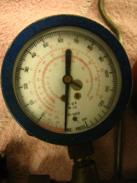
On Friday the 11th the new hose showed up and in no
time, I had it installed and started pumping the system down. 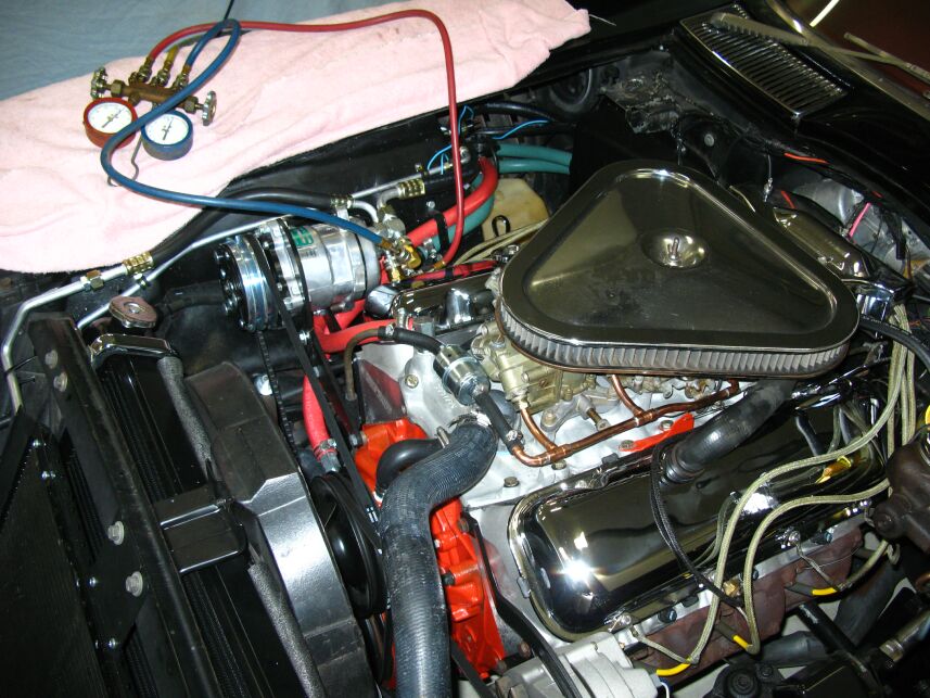 Vintage
Air says if it's not 85º outside, you should run the engine to
warm things up before evacuating the system. I not only did that
but I set up the shop heater to keep things warm while pumping it
down. I also used a heat gun on the dryer. After pumping
the system for an hour, I sealed it off and watched the vacuum and
check for leaks. It
held fine for 15 minutes so then I purged the system with Freon 134 and
pumped it for another 30 minutes. That should ensure it is about
as dry as I can possibly make it. Vintage Air says the 134 system
takes 1.8 lbs. (28.8 oz.) of refrigerant. After charging, the air
temperature out of the center ducts (closest to the evaporator) was
36º. Not bad! That's going to be NICE on a hot
day. I took it for a drive and the air temperature out of the
duct ran between 36 and 42º. Of course it's only 48 outside
but the compressor LED I installed earlier shows the duty cycle of the
compressor to be VERY short in these temperatures, just as it ought to
be. With that, we put the hood back on the car and other than the
seats and door panels, it's done. Well, maybe not DONE but it's
ready to drive!
Vintage
Air says if it's not 85º outside, you should run the engine to
warm things up before evacuating the system. I not only did that
but I set up the shop heater to keep things warm while pumping it
down. I also used a heat gun on the dryer. After pumping
the system for an hour, I sealed it off and watched the vacuum and
check for leaks. It
held fine for 15 minutes so then I purged the system with Freon 134 and
pumped it for another 30 minutes. That should ensure it is about
as dry as I can possibly make it. Vintage Air says the 134 system
takes 1.8 lbs. (28.8 oz.) of refrigerant. After charging, the air
temperature out of the center ducts (closest to the evaporator) was
36º. Not bad! That's going to be NICE on a hot
day. I took it for a drive and the air temperature out of the
duct ran between 36 and 42º. Of course it's only 48 outside
but the compressor LED I installed earlier shows the duty cycle of the
compressor to be VERY short in these temperatures, just as it ought to
be. With that, we put the hood back on the car and other than the
seats and door panels, it's done. Well, maybe not DONE but it's
ready to drive!I'm very pleased with the Vintage Air kit for the Corvette. It's a bit of work to install and I probably made it a bit harder by making sure everything fit just as it's supposed to but I think it will pay off in the future. I can't say enough about Vintage Air as a company. They build a NICE product and support it very well. No doubt I would recommend them to anyone wanting to air condition a car that didn't come with factory air. All in all, I love it!
__________________________________________________________________________________________________________________________________________________________
Last Updated:
4/1/2011: Added driver's side dash pictures