As delivered, the Ultrasport uses 3 stop/turn lamps per side. The lamps are #3157 and each stop filament draws just over 2 amps per lamp. The original wiring caused significant voltage drop at the stop lamps which made the lamps somewhat dimmer than they should be. In addition, the current flow made the original 18 gauge wiring under the dash get rather warm. I measured the voltage at the trailer connector with the engine off and found that with 12.4 volts at the battery, I had less that 10.0 volts at the connector. In addition, I had concerns as to the capability of the factory wiring to handle the load with a trailer connected or the lighting on a toad. To address this, I isolated all the rear lighting with three relays.
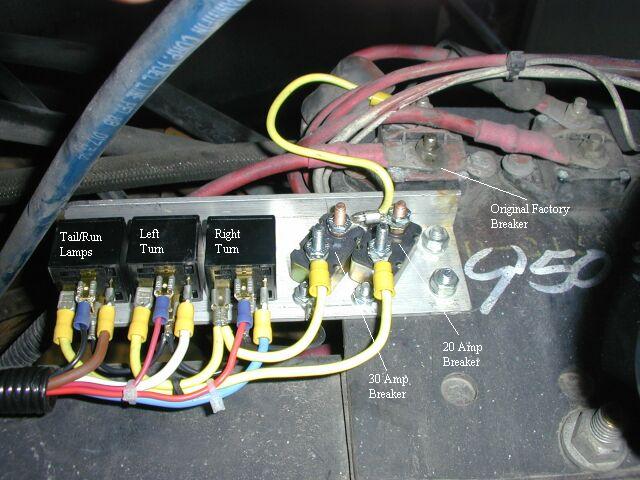
Hers's how I did it: There is a factory bracket that holds two circuit breakers and a solenoid that is mounted on the frame rail on the right side of the engine. I fabricated another bracket with three 30 amp relays and two circuit breakers and mounted it to this original bracket. The relays are “Heavy Duty, Baja Tough” part number DF005 relays sold under the Federal Mogul brand name obtained from Auto Zone and are normally used for controlling accessory lighting. One relay was used for left turn/stop, one for right turn/stop and one for tail/clearance lamps. I used 18 gauge wire to control the relays and 12 gauge for the high current side.
It so happens that the harness for the rear lighting runs along the frame rail right below this bracket. I opened the harness and found the wires for right turn/stop, left turn/stop and the tail lamps. Incidentally, the tail lamp wire supplies ALL the running lights on the rear and the center clearance lamps on the sides of the coach. This is something like 16 lamps alone! I cut the original wires and used the end FROM the front of the coach to control the relay coil. The wire TO the rear lamps is connected to the normally open (NO) contact on each relay. I supplied power to the two stop lamp relays through a 30 amp circuit breaker and the tail lamp relay through a 20 amp breaker. The power for the breakers is taken from the battery side of one of the original breakers on the above mentioned panel.
The wire color codes and sizes from the added 30 amp relays are as follows:
| RELAY POSITION BACK (running lamps) CENTER (left turn/stop) FRONT (right turn/stop) |
POWER OUTPUT 12 GA BROWN 12 GA WHITE 12 GA BLUE |
CONTROL 18 GA BLACK 18 GA RED 18 GA ORANGE |
After this modification, the stop and tail lamps are MUCH
brighter.
When I installed the modification, I did the left side first and
compared
the brightness using the hazard flashers. This makes a DRAMATIC
difference.
I tried to get a picture of the difference but it is not nearly as
dramatic
as in real life. An added benefit is that the load on the
headlamp
switch, flashers and wiring is now MUCH lower. This is a very
economical
modification and makes a MAJOR difference in the rear lighting on the
coach.
I don't think you can have too much light when it comes to stop lamps.
|
|
This is a shot of the factory bracket with the new relay bracket attached. In this shot, you can see the original breaker above the added bracket. |
|
|
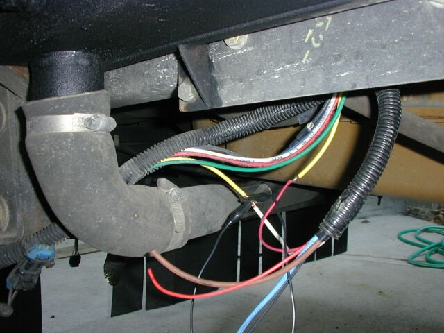
This is a shot of the harness connection point at the right rear frame rail. You can see the yellow wire (left turn) has been cut and the power FROM the relay (white) and the relay control wire (red) has been temporarily connected to test the system. |
|
|
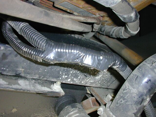
After soldering and heat shrinking all the necessary connections, the wires were all tucked back in the harness tube and the junction of the two tubes was taped up. Then the harness was pulled up and tie-wrapped to the frame rail up out of harm's way. |
E-mail me at ultrasport(REMOVE)@mail.com
© Copyright 2002, 2003, 2004 Steve Das
Last updated April 30, 2001