Purchased
from the Heathkit
Electronic Center
5050 FM 1960W #126
Due to a move to a
no antenna area, the amp was packed
away from
about 2000 to 2015 when it was put back in service.
When I built the amp, I installed an electronic bias
switching circuit from the May, '74 issue of QST. That
circuit had issues and resulted in
distortion (for unknown reasons) so I had redesigned
the circuit back in the '80's. That
circuit had failed so
after
reading numerous articles about how the 3-500 anodes (plates) need to
get red
for the getters to work, I removed the circuit from the amp and put it
back to
stock configuration.
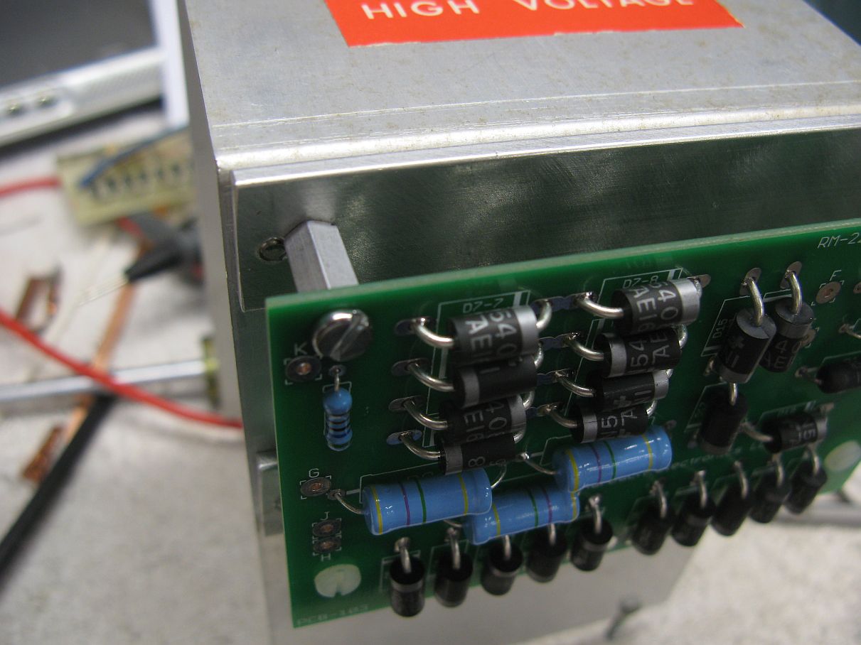
Installed
new high
voltage capacitor module from "Paul Kraemer" (W0UYA)
<elespe@lisco.com>
at Electronic Specialities in
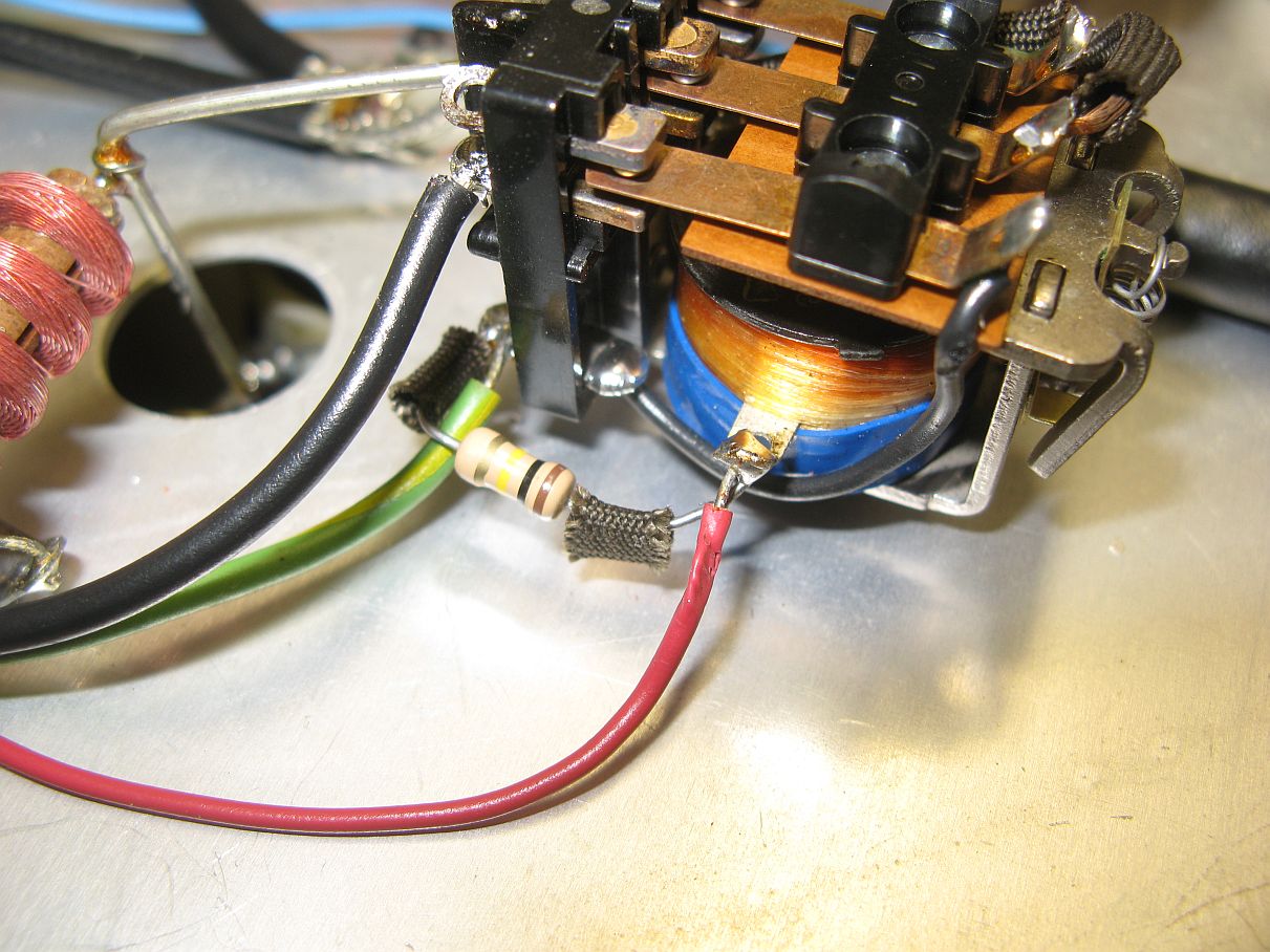
Resistive Bias Mod: I also did the "WY6K - An Essential Mod to the SB-220 and SB-221". There are two versions of this modification,. I did the second that positively biases the tubes off with 120 volts through a 100K resistor. This circuit biases the tubes into cutoff in RX mode by pulling the cathode up toward the 120 volt bias supply voltage through the 100k resistor. There will be some voltage drop across the resistor, but the cathode will still be close to 100 volts and firmly in cutoff. If the cathode shorts to ground through the grid, the current is limited to about 1 ma and the transformer will not melt down. Voile.
This mod is completed at the TR relay. Here is the before picture and here is the after.
When the T/R relay is switched into TX mode, an 8 diode string on the new Harbach diode board (replacing the original 5V zener) is connected to the center tap of the filament transformer, taking the cathode to + 6.8 volts and biasing the amp as intended for class AB2 operation. This is called "resistive bias", whereas the original circuit used "voltage bias".
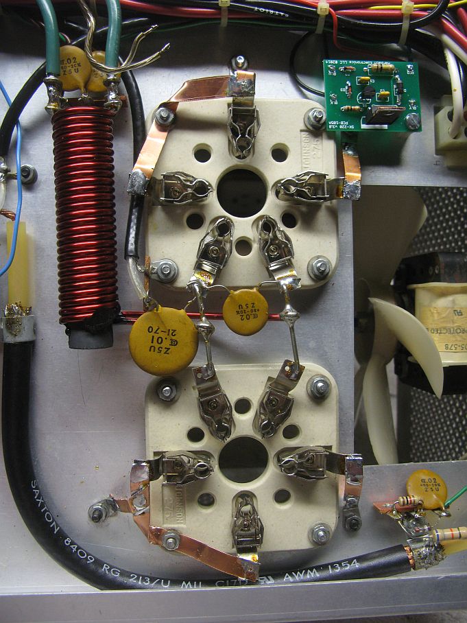
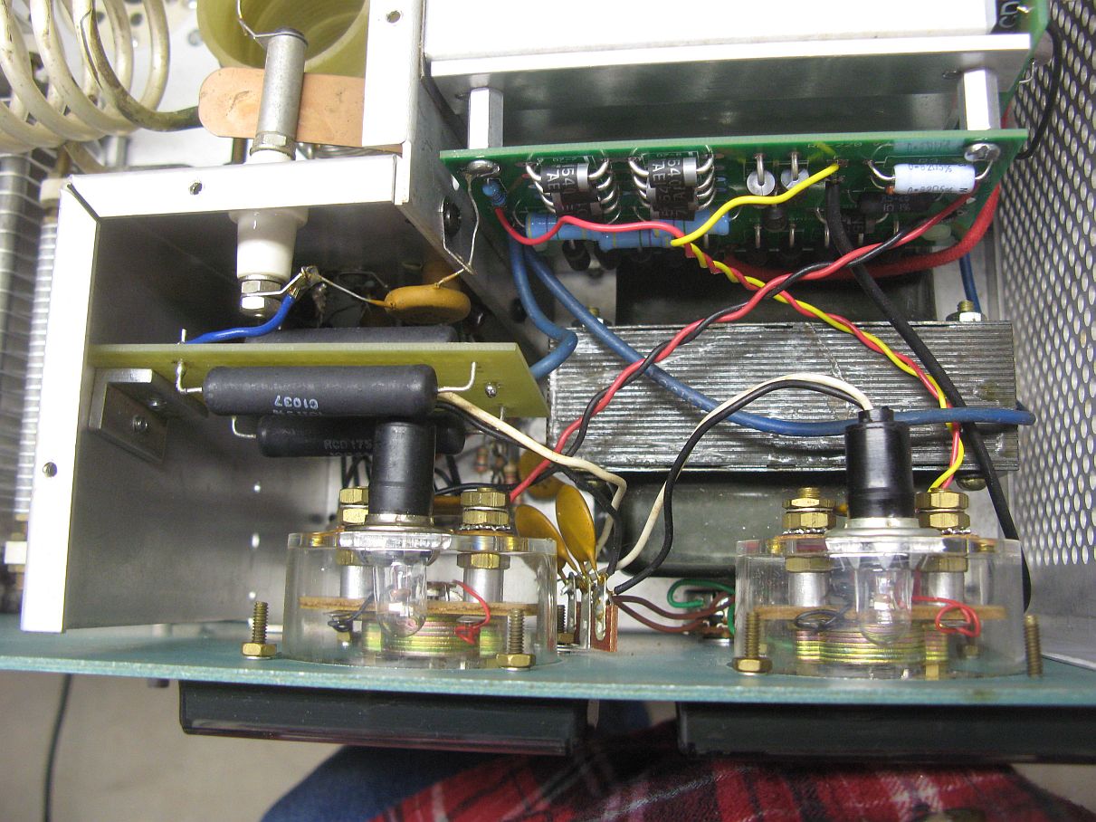
In addition, I removed
all the bypass
capacitors and chokes that connected the 3-500Z grids to ground
and
firmly grounded
them with .016 X 1/4 inch copper straps. Here's
a picture of that. This was
recommended in most of the articles about using the 3-500Z tubes in
grounded
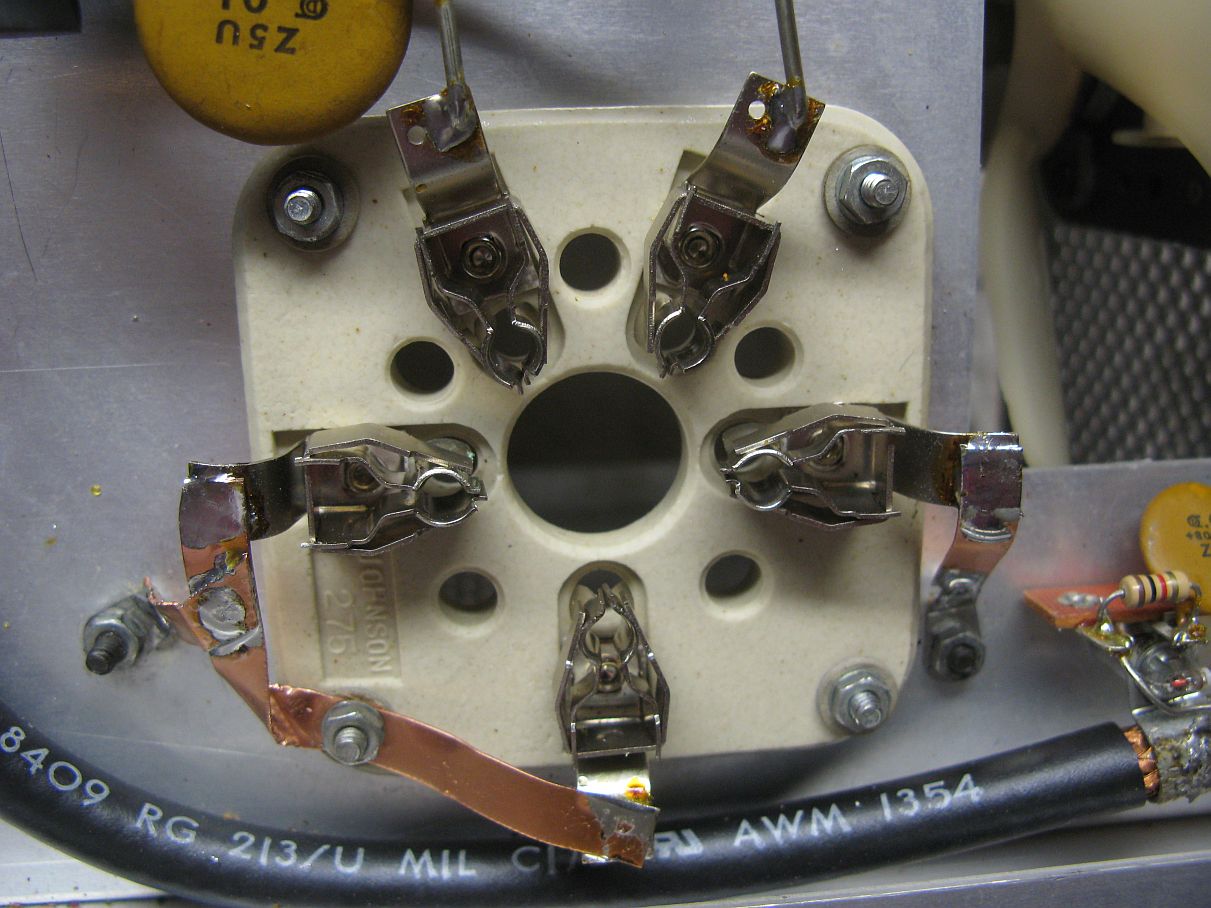
grid configuration. While you're there, it's a good idea to check
all of the pin connectors on the 3-500z sockets. On most of the
sockets Heath used, the clip that tensions the pins can be
removed and the contacts can be aligned to better fit the tube
pins. Also the clip can be bent to more evenly apply pressure to
the pin of the tube. I found several that didn't fit well and
fixed them. This will not only help with the grid connection but
the 3-500's have been known to get so hot as to melt the solder in the
filament pins (they're handling ~ 15 amps!) so a good connection there
is essential.
Filament/Bias
transformer failed: The amp was
powered up and the keying
relay would only buzz when keyed. It was
found that the 22μF capacitor on the 120 volt bias supply was HOT. The bias winding in the filament transformer
was shorted so the transformer was removed and sent to Gary Brown (1-207-942-5745)
at Transformer
Rewinding Service in
New Bias Power Supply Designed and Installed: Because the bias winding in the original Heath filament/bias transformer had failed and because it is relatively fragile, I decided to install a separate bias transformer. In the event of a bias problem again, it will be MUCH less expensive to repair. I selected a Triad FP88-65 PC mount transformer. This transformer has two 44 volt secondaries and a 110/220 volt primary and will deliver 65ma at 88 volts. It costs just under $11.00 from Mouser Electronics. The bias supply needs to deliver roughly 30 ma to power the keying relay (~26ma), the bias for the 3-500's (~1 ma), the current for the soft key board (~1ma) and ALC current (~2ma). The new power supply is mounted under the amplifier near the 120 volt terminal strip and is wired for 220 VAC only.
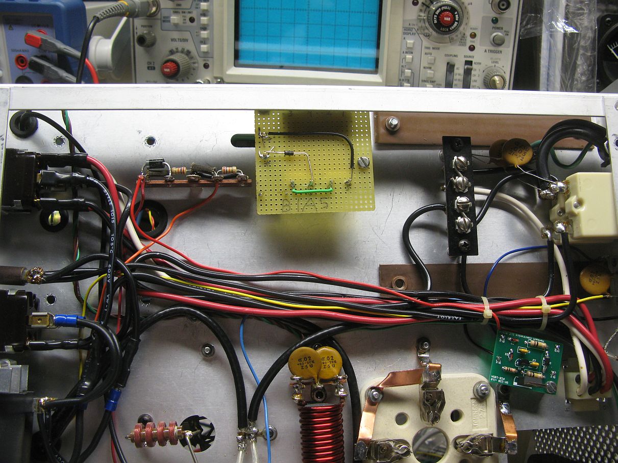
Each secondary winding is spec'd at
115-145 ohms (230-290 total DCR) so the
transformer will only deliver about 120ma when short circuited. Open circuit, the transformer delivers about
185 VDC through the half wave rectifier.

I realize the
wiring of the transformer appears a bit weird and you might think the
windings are in buck configuration but I drew it that way because of
the numbering of the pins on the actual transformer. When using
the transformer on 240 volts, pins
2&3 are wired together and the input is applied to 1 and 4.
Pins 2 and 3 are NOT side by side (as you can see HERE) on the transformer so I drew it
to represent the way the pins appear on the transformer. Likewise
on the secondary; pins 6 and 7 are not side by side so to series the
windings, pins 6&7 are tied together and 5 and 8 are the output.
The 120 volt, 5W zener (1N5380) has a temperature coefficient such that at operating temperature, the voltage rises to about 130VDC. At that voltage, it is only conducting about 15ma. Since the bias supply also runs the keying relay in the SB-221 and the ALC supply. When the relay is keyed on, it pulls about 23ma and the voltage drops to about 110VDC. The zener is then non conducting so the transformer load is never more than about 30ma for the relay current, the ALC supply, the soft key board and the bias to the 3-500Z's.
Amp
Wired for 220
Volts Only
In addition, per Heath Service Bulletin SB-220-27, (MSword
document) when
the
rewound filament/bias transformer from
The rebuilt amplifier now works great. Unkeyed
high voltage is now 2400 in CW and 3100
in SSB with 246 volts input. The key
down, no signal
plate
current runs ~100ma in CW and 150ma in SSB. I
measured the filament voltage from the rewound
transformer before and
after installing the tubes and found the open circuit voltage to be
5.287 volts
AC and with the tubes installed, it is running 4.86 volts.
Tuned to 14.260 and driving a 50 ohm oil filled dummy
load, it does
1100 watts key down in CW and over 1600 peak in SSB when driven with my
TS-520S. Since the maximum allowed
power on the amateur bands is 1500 watts peak, this amplifier produces
the full
legal limit. Not bad!
Now, here's a "freebee" for
reading all this stuff. There's a device out there called a "3898
pecker".... Look it up on Google. It's real. The best
link I have found is at http://www.iol.ie/~bravo/Woodpecker.htm
You can read all about it there but almost as a lark, I built one,
exactly as shown in the article. I got all the parts (except for
the 74LS13) from Mouser for about $15.00. The 74LS13 is now
obsolete but I found a guy that had 25 for a good price so I have a few
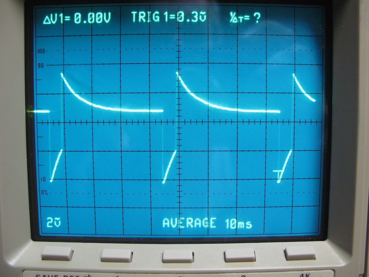
spares. The pecker puts out a very strange waveform that is fed
into the audio in of your transmitter and then you tune the finals (or
your amp) in SSB. The result is EXACT tuning with almost no
stress on the finals, even if you're way off resonance. You have
to use a peak reading wattmeter to tune because the duty cycle of the
pecker is so short. The article says 10% but looking
at it on a scope it
may be less than that. Using my Autek WM 1 peak reading meter, my
TS-520S shows 145 watts in SSB and if I switch the meter over to
average, it shows LESS THAN 1... yes ONE watt! I don't believe
the absolute watt numbers are right because of the strange waveform but
I do believe the ratios.
I hope this helps others make this great amplifier even better.
With these updates and mods, the SB-220/221 amplifiers should be around
for a long time to come.
73,
Steve - N4BOS
This page last updated:
April 30, 2015 ... Initial Release
May 2, 2015 ..... Cleaned up text, added clarification on bias transformer wiring.