Last updated 11/21/07
(Click on any picture to see larger view)
(Click on any picture to see larger view)
By the way, I hate to do this but just in case....
IF YOU DO ANY OF THESE MODIFICATIONS YOURSELF, YOU ASSUME ALL
LIABILITY!!
I CANNOT BE RESPONSIBLE FOR YOUR WORK. MAKE ANY CHANGES AT
YOUR OWN RISK!!!
CONTENTS
(click subject below to view)
Crash Bar
Alarm LED
Outside 20 Amp Outlets
Engine Draft Tube
Propane Quick
Disconnect
Furnace Control Switch
Under Coach Sewer Hose Carrier
Engine Grill Modification
Side Turn Indicators
CB Antenna Fix
and 2 Meter
Rig
Resistor in Vent Hood
Water Surge Tank
Digital Volt Meter
Inverter
Anti Theft Switch
Under Counter Lighting
Heater Outlet
Basement Drawers
Stainless Screws in Freezer
30 Amp Power Cord
Compressor LED
Voltage & Polarity
Monitors
Engine Air Inlet
Storage Door Struts
Mineral Oil in Batteries
Water Sediment Filter
Awning Lock
Dash AC Filter
Replaced Shower Door Sweep
Brake Buddy Monitor and Control
HF
Antenna Mount
Added
Second Pair of Golf Cart Batteries
Added
Link-10 Battery Monitor
Installed Icom IC-208H
Amateur Radio
Inverter Remote Control Switch
Satellite Wiring
TV Line Amplifier
Installed Olympian Wave 6 Heater
Fan inside Norcold Refrigerator
 Battery Filler
CRASH BAR
 On
Valentine's Day, 2001, I got a call that my storage area had been
broken
into and the motorhome damaged. As it turned out, they had bashed
the roll-up door with some kind of vehicle and smashed the ladder up
against
the fiberglass, fracturing it under the paint and went under the coach
enough to smash the license plate up underneath the valence panel.. I
don't
believe they actually went into the storage area as nothing else seemed
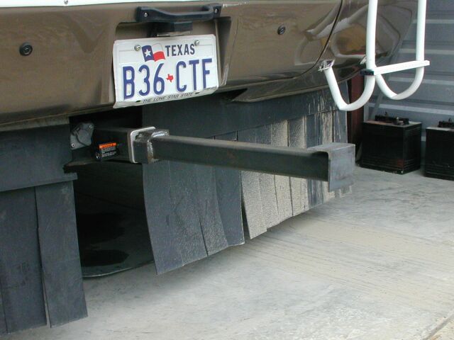
to be touched. After the break-in, I made up a "crash bar" that
goes
almost up against the inside of the roll-up door and locks into the
receiver
on the rear of the coach. Hopefully, if they try that again, it
will
hold the door back enough that the motorhome does not get hit as well
as
leave some nice damage on THEIR car instead and they will not be able
to
get into the storage area.
On
Valentine's Day, 2001, I got a call that my storage area had been
broken
into and the motorhome damaged. As it turned out, they had bashed
the roll-up door with some kind of vehicle and smashed the ladder up
against
the fiberglass, fracturing it under the paint and went under the coach
enough to smash the license plate up underneath the valence panel.. I
don't
believe they actually went into the storage area as nothing else seemed
to be touched. After the break-in, I made up a "crash bar" that
goes
almost up against the inside of the roll-up door and locks into the
receiver
on the rear of the coach. Hopefully, if they try that again, it
will
hold the door back enough that the motorhome does not get hit as well
as
leave some nice damage on THEIR car instead and they will not be able
to
get into the storage area.
INSTALLED ALARM LED BY DOOR
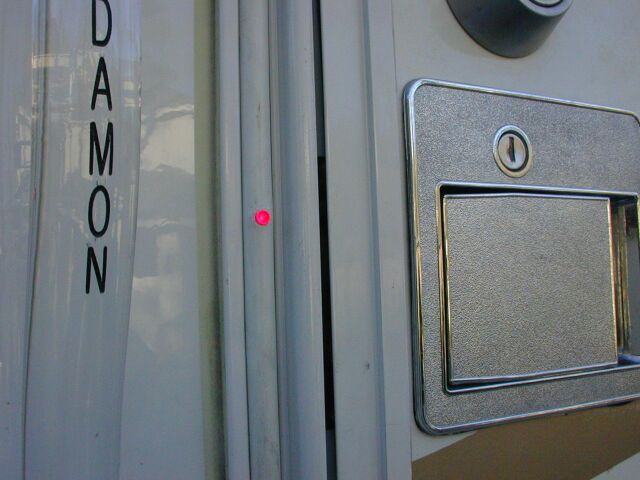
 After
the break-in, I decided to add a couple of things to try to deter them
if they DO get into the storage area. Hopefully, these will also
help in a campground. I used a flasher LED from Fry’s.
Installed
in the vinyl trim strip on the left side of the door next to the
handle.
It's wired to the +12V that is available at the Intellitec battery
switch
panel next to the door just inside the coach. Although the LED
has
an internal current limiting resistor built in, I added a 1200
ohm
resistor so the LED draws only about 5 ma when it flashes. In
addition,
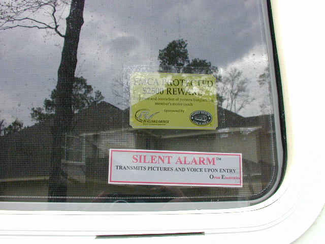
I made up a warning decal and put that on the side window. Maybe
it will help a little..
After
the break-in, I decided to add a couple of things to try to deter them
if they DO get into the storage area. Hopefully, these will also
help in a campground. I used a flasher LED from Fry’s.
Installed
in the vinyl trim strip on the left side of the door next to the
handle.
It's wired to the +12V that is available at the Intellitec battery
switch
panel next to the door just inside the coach. Although the LED
has
an internal current limiting resistor built in, I added a 1200
ohm
resistor so the LED draws only about 5 ma when it flashes. In
addition,
I made up a warning decal and put that on the side window. Maybe
it will help a little..
INSTALLED OUTSIDE 20 AMP OUTLETS
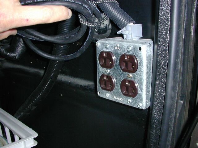 To
do this, it was necessary to run two, 12/2 with ground wires from the
rear
fuse box to the outside storage compartment. This was done by
snaking
the wire through the existing chaise on the left side of the coach
(inside)
and then through the floor under the stove to get to the
compartment.
I installed two 20 amp breakers in the fuse box and 20 amp plugs in the
compartment. Since these receptacles are after the transfer
switch,
they are connected to both sides of the incoming 220 line or to each
side
of the generator, depending on the source of the AC voltage.
To
do this, it was necessary to run two, 12/2 with ground wires from the
rear
fuse box to the outside storage compartment. This was done by
snaking
the wire through the existing chaise on the left side of the coach
(inside)
and then through the floor under the stove to get to the
compartment.
I installed two 20 amp breakers in the fuse box and 20 amp plugs in the
compartment. Since these receptacles are after the transfer
switch,
they are connected to both sides of the incoming 220 line or to each
side
of the generator, depending on the source of the AC voltage.
MODIFIED ENGINE DRAFT TUBE
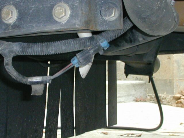 As
originally supplied, the draft tube from the engine is above the frame
rail on the passenger side of the coach. This results in a pretty
oily frame rail as well as leading to clogging of the intercooler with
oily dirt. There supposedly was a service bulletin on this from
Caterpillar
that lowered it below the frame rail somehow but Houston Freightliner
knew
nothing about it so I decided to fix it myself. I added a “in
line
trap” piece of PVC obtained from Home Depot. I cut the end off at
an angle to create a draft when moving down the road. The inside
diameter of the original draft hose is 1 inch. The OD of the PVC
trap is about 1 1/16. A clamp holds it in place in the
hose.
The trap shape just clears the frame rail and the end is now about 3
inches
below the frame rail.
As
originally supplied, the draft tube from the engine is above the frame
rail on the passenger side of the coach. This results in a pretty
oily frame rail as well as leading to clogging of the intercooler with
oily dirt. There supposedly was a service bulletin on this from
Caterpillar
that lowered it below the frame rail somehow but Houston Freightliner
knew
nothing about it so I decided to fix it myself. I added a “in
line
trap” piece of PVC obtained from Home Depot. I cut the end off at
an angle to create a draft when moving down the road. The inside
diameter of the original draft hose is 1 inch. The OD of the PVC
trap is about 1 1/16. A clamp holds it in place in the
hose.
The trap shape just clears the frame rail and the end is now about 3
inches
below the frame rail.
INSTALLED QUICK DISCONNECT FOR
PROPANE

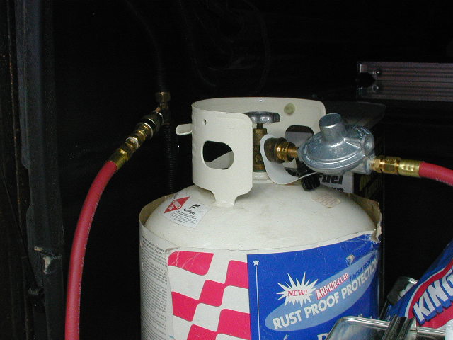 When
dry camped, it seemed that the batteries would not hold up as long as I
would have expected. I checked the parasitic current draw and
found
that almost 1 amp was being drawn from the batteries by the propane
solenoid
mounted on the tank. To address this, I installed a female quick
disconnect plumbed into the propane line that goes through the side
compartment
up to the refrigerator on the right side of the coach. I bought a
new high volume regulator and 5 feet of hose and installed the male
part
of the quick disconnect on the end of the hose. Now when we dry
camp,
we can run the refrigerator off an extra 20 pound propane bottle and
save
over 20 amp hours of battery power per day. The external bottle
and
regulator will supply enough propane to run all the gas appliances
including
the generator if need be. Nice back-up. Incidentally, the
whole
setup cost me $35.00! (I had the bottle) UPDATE:
Originally, we would take the batteries down about 50% in two
days.
Using the external bottle, we recently went 5 days before they were at
50%. I ran the refrigerator on the 20 pound bottle (in pretty
moderate
weather) for 6 days and had over half a bottle left.
When
dry camped, it seemed that the batteries would not hold up as long as I
would have expected. I checked the parasitic current draw and
found
that almost 1 amp was being drawn from the batteries by the propane
solenoid
mounted on the tank. To address this, I installed a female quick
disconnect plumbed into the propane line that goes through the side
compartment
up to the refrigerator on the right side of the coach. I bought a
new high volume regulator and 5 feet of hose and installed the male
part
of the quick disconnect on the end of the hose. Now when we dry
camp,
we can run the refrigerator off an extra 20 pound propane bottle and
save
over 20 amp hours of battery power per day. The external bottle
and
regulator will supply enough propane to run all the gas appliances
including
the generator if need be. Nice back-up. Incidentally, the
whole
setup cost me $35.00! (I had the bottle) UPDATE:
Originally, we would take the batteries down about 50% in two
days.
Using the external bottle, we recently went 5 days before they were at
50%. I ran the refrigerator on the 20 pound bottle (in pretty
moderate
weather) for 6 days and had over half a bottle left.
INSTALLED FURNACE CONTROL
SWITCH
BY BED
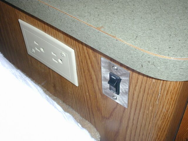 This
switch is in the thermostat control line and allows the furnace to be
turned
on or off from the bed. In this manner, we can sleep cool in the
winter but turn the furnace on in the morning before getting up.
The wire for this is 18/2 that was snaked through the chaise inside the
coach from the furnace to the rear power compartment where the switch
was
placed on the outside of the lower cabinet.
This
switch is in the thermostat control line and allows the furnace to be
turned
on or off from the bed. In this manner, we can sleep cool in the
winter but turn the furnace on in the morning before getting up.
The wire for this is 18/2 that was snaked through the chaise inside the
coach from the furnace to the rear power compartment where the switch
was
placed on the outside of the lower cabinet.
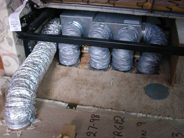
INSTALLED SEWER HOSE CARRIER UNDER
COACH

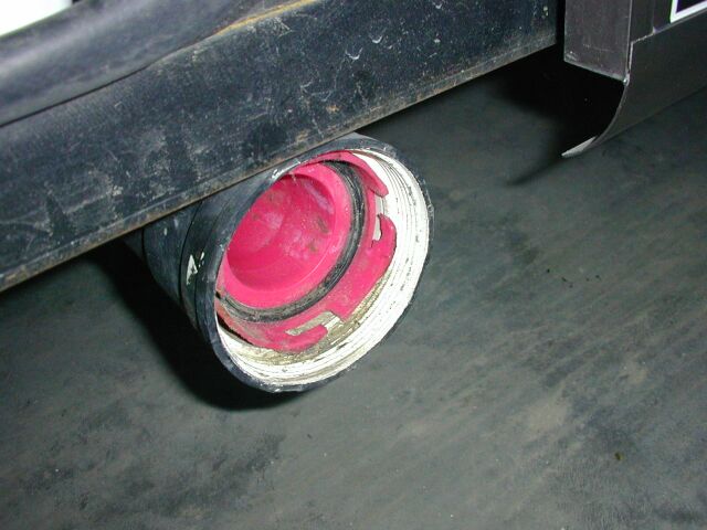
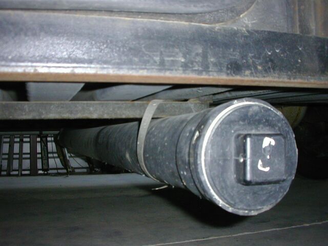 For
this carrier, I used perforated PVC drain pipe purchased from Home
Depot
and secured it up under the coach just ahead of the sewer dump
compartment.
The pipe was mounted using two long hose clamps and situated with the
holes
down to allow drainage. The cap is a 4 inch PVC pipe cap with a
plug.
The other end has a closed pipe cap glued on to seal it. As you
can
see, the sewer coupling just fits inside the cap and the cover holds it
all in. I painted the pipe flat black to blend in. I have used
this
for several years on other rigs and it works out very well.
For
this carrier, I used perforated PVC drain pipe purchased from Home
Depot
and secured it up under the coach just ahead of the sewer dump
compartment.
The pipe was mounted using two long hose clamps and situated with the
holes
down to allow drainage. The cap is a 4 inch PVC pipe cap with a
plug.
The other end has a closed pipe cap glued on to seal it. As you
can
see, the sewer coupling just fits inside the cap and the cover holds it
all in. I painted the pipe flat black to blend in. I have used
this
for several years on other rigs and it works out very well.
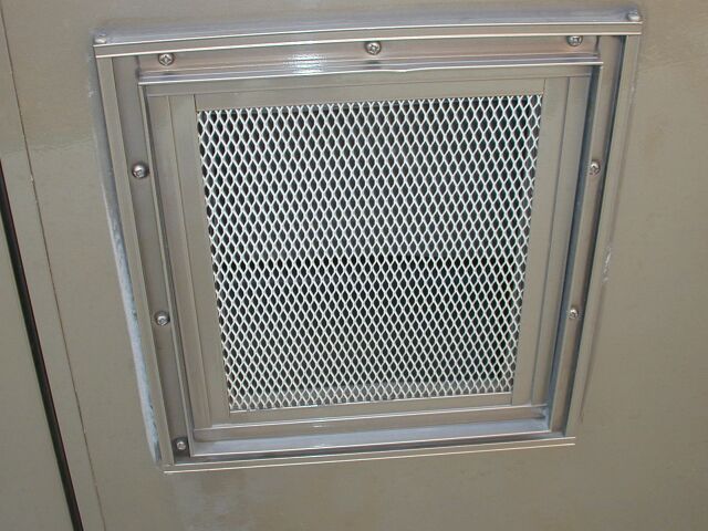
MODIFICATION TO
ENGINE
GRILLE FOR COOLING
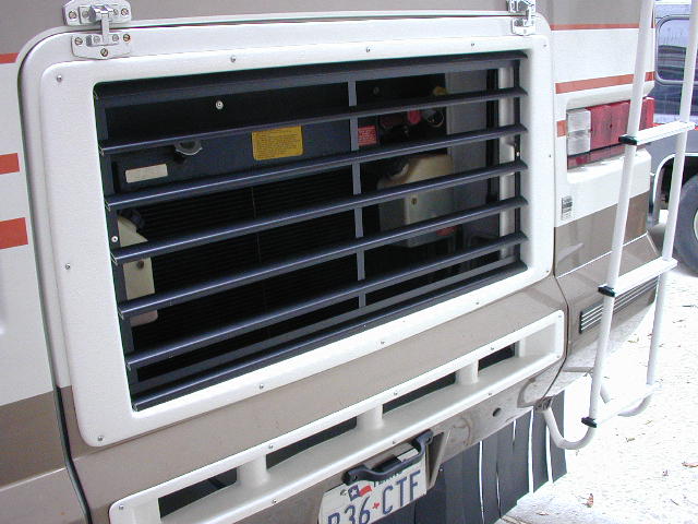 This
was a warranty recall by Damon to improve engine cooling while towing a
car. The modification was performed by Allstate RV (formerly
Burditt)
in Spring, TX. If I had it to do over, I would NOT let them
modify
the grille until I had overheating problems. The original looked
MUCH better in my opinion.
This
was a warranty recall by Damon to improve engine cooling while towing a
car. The modification was performed by Allstate RV (formerly
Burditt)
in Spring, TX. If I had it to do over, I would NOT let them
modify
the grille until I had overheating problems. The original looked
MUCH better in my opinion.
INSTALLED SIDE TURN INDICATOR
LAMPS
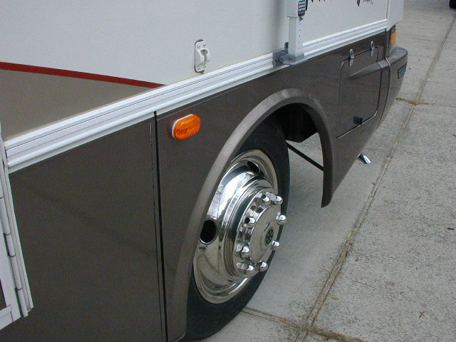 I
installed dual bulb clearance lamps and wired them as clearance/turn
lamps.
I mounted the lamps just at the top rear of the fiberglass front wheel
housing. The lamps were originally designed to ground to the
frame
through the mounting screws. Since this is a fiberglass body, and
I needed access to both power and ground, I soldered in a ground wire
to
the frame of the lamps. The wiring to the coach is very
straightforward;
the new “ground” wire from the lamp goes to the hot side of the turn
signal
filament (white wire) of the front turn signal. The “+” lead from
the lamp goes to the hot side of the running or parking lamp (green
wire).
Now, when the turn signals are turned on and the running lamps are off
(headlights or parking lights off), the added clearance lamp flashes in
synch with them. Under this condition, the lamp is grounded
through
the parking lamp filament. When the running lamps are on, the
clearance
lamp is on as well, getting its ground through the turn signal
filament.
When the turn signal is turned on now, the clearance lamp flashes out
of
synch with the turn signal. In this condition, ground is obtained
through the turn signal filament when the turn signal is in the off
mode.
I
installed dual bulb clearance lamps and wired them as clearance/turn
lamps.
I mounted the lamps just at the top rear of the fiberglass front wheel
housing. The lamps were originally designed to ground to the
frame
through the mounting screws. Since this is a fiberglass body, and
I needed access to both power and ground, I soldered in a ground wire
to
the frame of the lamps. The wiring to the coach is very
straightforward;
the new “ground” wire from the lamp goes to the hot side of the turn
signal
filament (white wire) of the front turn signal. The “+” lead from
the lamp goes to the hot side of the running or parking lamp (green
wire).
Now, when the turn signals are turned on and the running lamps are off
(headlights or parking lights off), the added clearance lamp flashes in
synch with them. Under this condition, the lamp is grounded
through
the parking lamp filament. When the running lamps are on, the
clearance
lamp is on as well, getting its ground through the turn signal
filament.
When the turn signal is turned on now, the clearance lamp flashes out
of
synch with the turn signal. In this condition, ground is obtained
through the turn signal filament when the turn signal is in the off
mode.
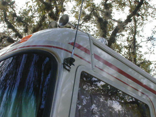
FIXED CB ANTENNA
AND
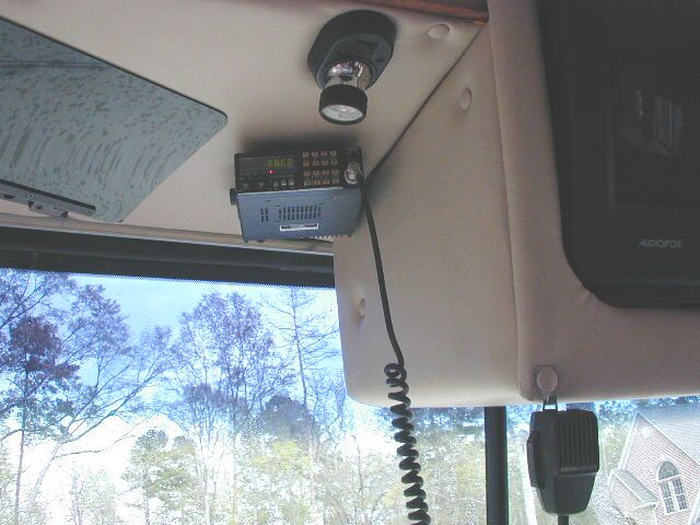
INSTALLED CB RADIO and AMATEUR 2 METER RIG
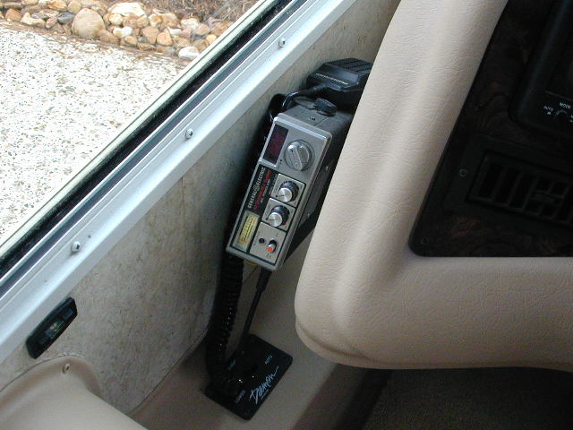
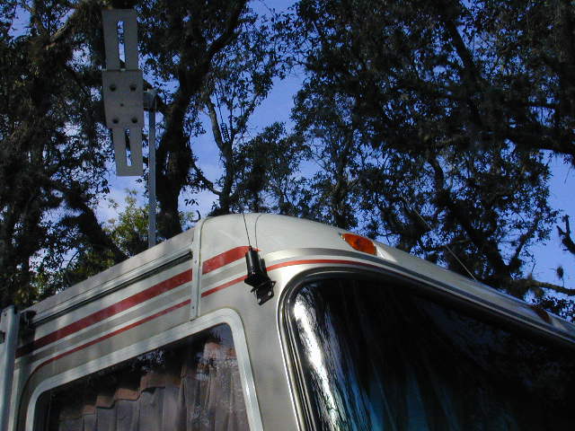 The
factory
installed CB antenna had an infinite SWR. I fixed that by
adding
a piece of braid for a counterpoise to the inside of the mount where
the
bolts came through the fiberglass. The braid now hangs down under
the cover on the driver’s side. After the addition of the braid,
the SWR was 1.5 to 1. I then installed a small GE
CB radio with the bracket mounted in front of the transmission
control
console on the wall. It is wired such that it is on with the
ignition
switch. I also installed my
Azden
two meter rig under the shelf over the driver’s seat using one of
the
screws that was originally there. I hid the wires in the gap of
the
trim panel and snaked them to the lamp that is located near the radio
where
I picked up power. I know, I know, I was supposed to go all the
way
to the battery with the wiring but this thing only draws about 4 amps
on
transmit and works fine this way... and it was MUCH easier. I
used
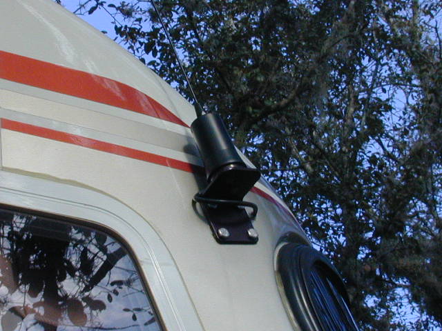
a Larson NMO2/70BCO
dual band antenna mounted on a Maxrad
BMMB34 mirror mount mounted to the fiberglass on the right side of
the coach, just behind the windshield. The Larson antenna is a
co-linear
antenna with an air wound coil in the middle. The antenna can be
bent double and will return to its original shape. Just the
ticket
to combat the trees in some campgrounds. On a recent trip to
Florida
the antenna performed very well. I was able to hit repeaters on
the
normal fringe areas and simplex operation was very satisfactory.
The
factory
installed CB antenna had an infinite SWR. I fixed that by
adding
a piece of braid for a counterpoise to the inside of the mount where
the
bolts came through the fiberglass. The braid now hangs down under
the cover on the driver’s side. After the addition of the braid,
the SWR was 1.5 to 1. I then installed a small GE
CB radio with the bracket mounted in front of the transmission
control
console on the wall. It is wired such that it is on with the
ignition
switch. I also installed my
Azden
two meter rig under the shelf over the driver’s seat using one of
the
screws that was originally there. I hid the wires in the gap of
the
trim panel and snaked them to the lamp that is located near the radio
where
I picked up power. I know, I know, I was supposed to go all the
way
to the battery with the wiring but this thing only draws about 4 amps
on
transmit and works fine this way... and it was MUCH easier. I
used
a Larson NMO2/70BCO
dual band antenna mounted on a Maxrad
BMMB34 mirror mount mounted to the fiberglass on the right side of
the coach, just behind the windshield. The Larson antenna is a
co-linear
antenna with an air wound coil in the middle. The antenna can be
bent double and will return to its original shape. Just the
ticket
to combat the trees in some campgrounds. On a recent trip to
Florida
the antenna performed very well. I was able to hit repeaters on
the
normal fringe areas and simplex operation was very satisfactory.
INSTALLED RESISTOR IN VENT
HOOD
FAN CIRCUIT
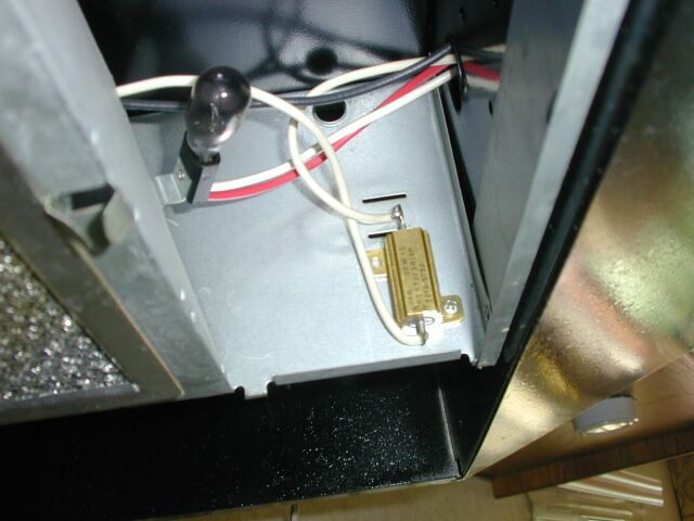 The
fan in the vent hood over the cook top would literally scream and there
was a vibration that I was not able to remove. I fixed the
problem
by putting a 3.15 ohm 20 watt resistor in series with the fan to slow
it
a bit. Seems to work fine now and the vibration is gone.
The
fan in the vent hood over the cook top would literally scream and there
was a vibration that I was not able to remove. I fixed the
problem
by putting a 3.15 ohm 20 watt resistor in series with the fan to slow
it
a bit. Seems to work fine now and the vibration is gone.
INSTALLED WATER PRESSURE
SURGE TANK
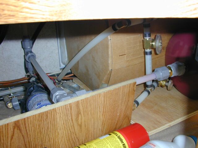
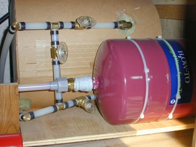 I
installed a 2.2 gallon pre-charged water reserve tank under the kitchen
sink. The tank came from Home Depot and was very
inexpensive.
The pressure is set for 20 PSI. I put a PEX “T” in the cold water
line up to the kitchen sink and ran PEX tubing to the tank. This
stopped the surging of the water pump and we can now wash hands or
flush
the toilet several times without the water pump even turning on.
I
installed a 2.2 gallon pre-charged water reserve tank under the kitchen
sink. The tank came from Home Depot and was very
inexpensive.
The pressure is set for 20 PSI. I put a PEX “T” in the cold water
line up to the kitchen sink and ran PEX tubing to the tank. This
stopped the surging of the water pump and we can now wash hands or
flush
the toilet several times without the water pump even turning on.
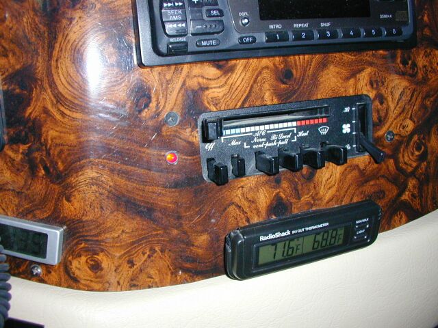
INSTALLED DIGITAL VOLT METER ON
DASH
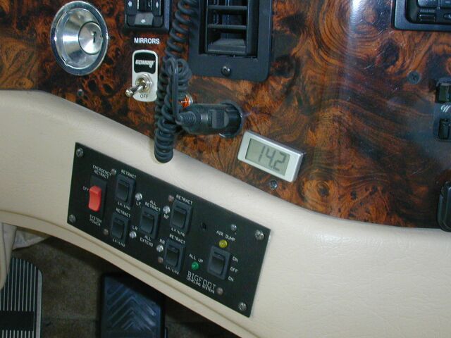 This
is a “Lascar” model EMV 1200 purchased from Allied Electronics. It is a
self powered (only has two wires) 3 digit digital volt meter.
This
is a slick little voltmeter that mounts using one small hole. The
wires run out through the center of the mounting stud. It is
wired
to the radio power lead which comes directly from the Intellitec
controller.
In this manner, it reads the voltage on the lighting buss in the
coach.
If the coach is plugged in and the house batteries are disconnected, it
reads converter output voltage. When dry camping, it reads the
voltage
on the house batteries. Great for telling the charge status of
the
batteries as we drive or when we are dry camping.
This
is a “Lascar” model EMV 1200 purchased from Allied Electronics. It is a
self powered (only has two wires) 3 digit digital volt meter.
This
is a slick little voltmeter that mounts using one small hole. The
wires run out through the center of the mounting stud. It is
wired
to the radio power lead which comes directly from the Intellitec
controller.
In this manner, it reads the voltage on the lighting buss in the
coach.
If the coach is plugged in and the house batteries are disconnected, it
reads converter output voltage. When dry camping, it reads the
voltage
on the house batteries. Great for telling the charge status of
the
batteries as we drive or when we are dry camping.
INSTALLED STATPOWER PROwatt 800 INVERTER
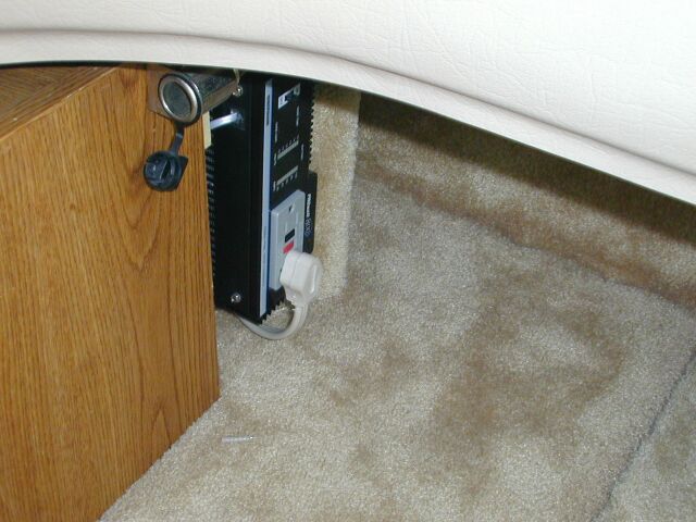 This
inverter will deliver 1000 watts continuously and a 2000 watt
surge.
Used #4 gauge welding cable and a TRACE 110 amp “T” series fuse.
The unit is wired directly to the coach batteries. The inverter
was
installed in the front of the coach right behind the center console for
a short run to the coach batteries. A 14/3 extension cord for the
115 volts was snaked through the cable chaise on the left side of the
coach
to the bedroom front power panel where it is connected to the
“receptacle”
and the “GFI” circuits with a transfer relay. The inverter drives
the relay coil such that if the inverter is on, the receptacle and GFI
circuits are powered from the inverter. If the inverter is off,
(and
the relay in its NC position) the circuits are tied to their original
15
amp breakers. I also added an indicator lamp on the dash to
indicate
when the inverter is on and a master disconnect switch on the
console.
These circuits power all the 115 volt outlets in the coach as well as
the
refrigerator. When under way, we use the inverter and run the
fridge
on 110. It is very nice to start out in the morning and fire up
the
coffee pot without having to start the generator. 1000 watts will
also run the toaster (not at the same time as the coffee pot) for that
english muffin while I drive! I also installed an accessory 12
volt
cigarette style outlet using a #12 wire and a 30 amp fuse from the
coach
battery. This allows relatively high power devices (like a
Peltier
icebox) to be run while on the road.
This
inverter will deliver 1000 watts continuously and a 2000 watt
surge.
Used #4 gauge welding cable and a TRACE 110 amp “T” series fuse.
The unit is wired directly to the coach batteries. The inverter
was
installed in the front of the coach right behind the center console for
a short run to the coach batteries. A 14/3 extension cord for the
115 volts was snaked through the cable chaise on the left side of the
coach
to the bedroom front power panel where it is connected to the
“receptacle”
and the “GFI” circuits with a transfer relay. The inverter drives
the relay coil such that if the inverter is on, the receptacle and GFI
circuits are powered from the inverter. If the inverter is off,
(and
the relay in its NC position) the circuits are tied to their original
15
amp breakers. I also added an indicator lamp on the dash to
indicate
when the inverter is on and a master disconnect switch on the
console.
These circuits power all the 115 volt outlets in the coach as well as
the
refrigerator. When under way, we use the inverter and run the
fridge
on 110. It is very nice to start out in the morning and fire up
the
coffee pot without having to start the generator. 1000 watts will
also run the toaster (not at the same time as the coffee pot) for that
english muffin while I drive! I also installed an accessory 12
volt
cigarette style outlet using a #12 wire and a 30 amp fuse from the
coach
battery. This allows relatively high power devices (like a
Peltier
icebox) to be run while on the road.
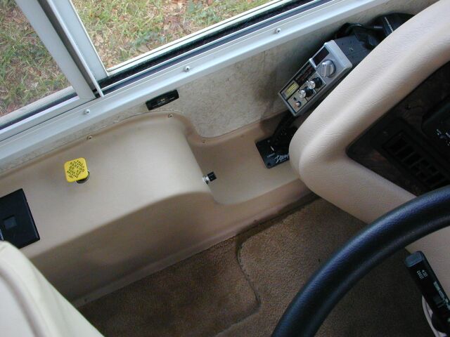
INSTALLED ANTI THEFT SWITCH
![]() This
switch is a 30 amp ignition switch mounted on the cover over the
transmission
controller. The switch is in series with the “battery power” lead
to the Allison controller. With the switch off, the engine
starter
will not engage. If the engine is running, turning the switch off
illuminates the “DO NOT SHIFT” lamp on the dash and the controller is
turned
off. There is no way to shift the transmission out of neutral
with
the switch off. You can set the fast idle and remove the
anti-theft
key and not worry about the coach being driven away. Doing this
sets
a “23 12” code in the Allison computer but everything works
normally.
When we park the coach, I remove the key and the engine can't even be
started.
This
switch is a 30 amp ignition switch mounted on the cover over the
transmission
controller. The switch is in series with the “battery power” lead
to the Allison controller. With the switch off, the engine
starter
will not engage. If the engine is running, turning the switch off
illuminates the “DO NOT SHIFT” lamp on the dash and the controller is
turned
off. There is no way to shift the transmission out of neutral
with
the switch off. You can set the fast idle and remove the
anti-theft
key and not worry about the coach being driven away. Doing this
sets
a “23 12” code in the Allison computer but everything works
normally.
When we park the coach, I remove the key and the engine can't even be
started.
INSTALLED UNDER COUNTER
LIGHTING
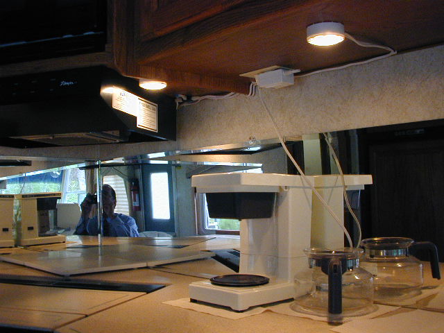 My
wife complained that the counter area was a little too dark. To
address
this, I used a three halogen lamp kit purchased from Home Depot for
$15.00.
The lights are installed in the kitchen area on either side of the vent
hood. I used the supplied 120 V transformer so we have to either
be plugged in or use the inverter to make them work. They are
running
on 11.5 volts off the transformer. If I had wired them to the house 12V
supply, they would have seen nearly 14 volts when plugged in and I was
worried about bulb life.
My
wife complained that the counter area was a little too dark. To
address
this, I used a three halogen lamp kit purchased from Home Depot for
$15.00.
The lights are installed in the kitchen area on either side of the vent
hood. I used the supplied 120 V transformer so we have to either
be plugged in or use the inverter to make them work. They are
running
on 11.5 volts off the transformer. If I had wired them to the house 12V
supply, they would have seen nearly 14 volts when plugged in and I was
worried about bulb life.
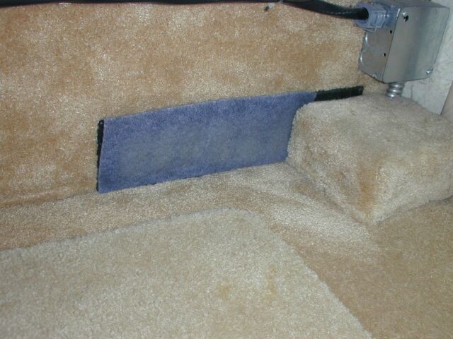
ADDED HEATER OUTLET DUCT
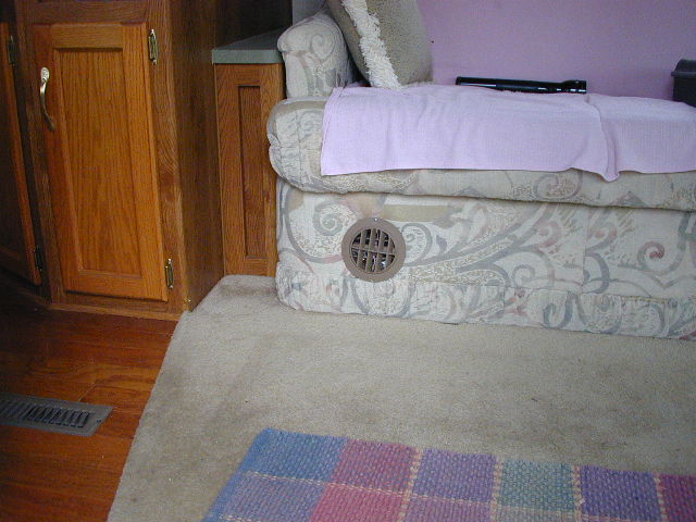
 When
heating the coach up from a cold start, the furnace would “limit” once
or twice and the burner would shut off while the fan continued to
run.
The burner would re-light in a minute or so and the heating would
resume.
It turned out that this was caused by the high temp limit switch
shutting
the burner off. The duct flanges were very poorly mounted to the
floor and allowed a LOT of heat to escape. This hot air was being
drawn right back into the furnace inlet and causing the high
temperature
limit switch to open. In addition, there was excess hose that was
kinked restricting the airflow. After repairing the heater
flanges
where they mounted to the floor of the coach and trimming off the
excess
hose, I added an additional duct to the furnace to increase
airflow.
The outlet was installed into the left side of the drop down panel
below
the sofa. It turned out that the required 4” hole was
already
in the wood behind the fabric. All I had to do was cut the fabric
and install the duct. Hydroflame sent me the new flange (at no
charge)
to mount in the unused hole in the front of the furnace. After
the
addition, the furnace will bring the coach up to temperature without
ever
limiting. The bedroom also heats MUCH better now as well.
When
heating the coach up from a cold start, the furnace would “limit” once
or twice and the burner would shut off while the fan continued to
run.
The burner would re-light in a minute or so and the heating would
resume.
It turned out that this was caused by the high temp limit switch
shutting
the burner off. The duct flanges were very poorly mounted to the
floor and allowed a LOT of heat to escape. This hot air was being
drawn right back into the furnace inlet and causing the high
temperature
limit switch to open. In addition, there was excess hose that was
kinked restricting the airflow. After repairing the heater
flanges
where they mounted to the floor of the coach and trimming off the
excess
hose, I added an additional duct to the furnace to increase
airflow.
The outlet was installed into the left side of the drop down panel
below
the sofa. It turned out that the required 4” hole was
already
in the wood behind the fabric. All I had to do was cut the fabric
and install the duct. Hydroflame sent me the new flange (at no
charge)
to mount in the unused hole in the front of the furnace. After
the
addition, the furnace will bring the coach up to temperature without
ever
limiting. The bedroom also heats MUCH better now as well.
BUILT DRAWERS FOR BASEMENT STORAGE
AREA
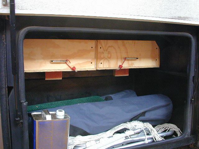
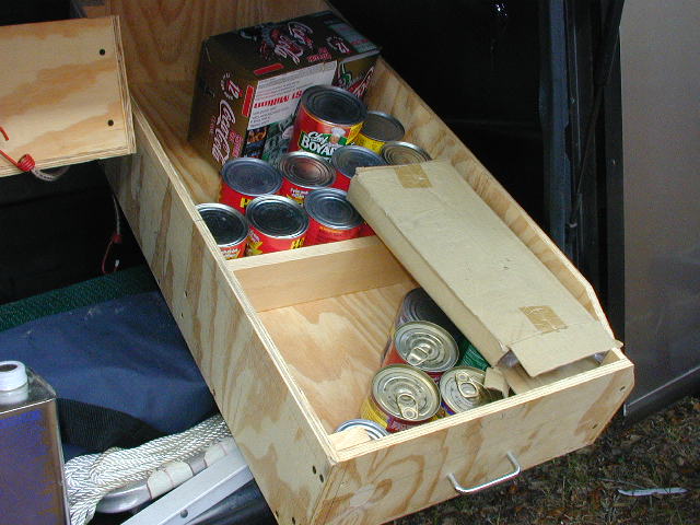 I
built and installed two drawers per side for under coach storage.
Each drawer goes half-way across the coach and is heavy enough to store
canned goods. They slide on wooden runners lubricated with
silicone
spray. In the first picture, you can see the block underneath
that
serves as a stop when you pull the drawer out and down to load or
unload.
As you can see, they are great for that extra stuff from the pantry.
I
built and installed two drawers per side for under coach storage.
Each drawer goes half-way across the coach and is heavy enough to store
canned goods. They slide on wooden runners lubricated with
silicone
spray. In the first picture, you can see the block underneath
that
serves as a stop when you pull the drawer out and down to load or
unload.
As you can see, they are great for that extra stuff from the pantry.
INSTALLED STAINLESS
SCREWS
IN FREEZER
 The
original screws and washers in the Norcold freezer compartment were
rusting
so I replaced them with stainless steel allen head screws and stainless
washers obtained from Home Depot.
The
original screws and washers in the Norcold freezer compartment were
rusting
so I replaced them with stainless steel allen head screws and stainless
washers obtained from Home Depot.
30 AMP POWER CORD
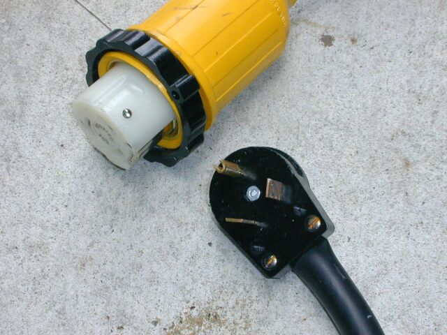 Most
places we go only have 30 amp service. In fact, a 50 amp RV
connector
is in reality 50 amp, 220 volt service. In most RV applications,
the second pole of the 220 line is used to run just the rear AC.
With most adapters, if you hook a 50 amp cord to 30 amp service the
rear
AC will not run. I made up a cord using a standard 30 amp plug
and
a Marino connector. I wired the two hot poles together inside the
Marino plug so that now, I can run either the front or the rear AC when
hooked up to 30 Amp service. As I recall, the connector is a
Marino
6364CRNS. Although these connectors are expensive, the
convenience
of not having to handle the 50 amp cord is worth it to me.
Most
places we go only have 30 amp service. In fact, a 50 amp RV
connector
is in reality 50 amp, 220 volt service. In most RV applications,
the second pole of the 220 line is used to run just the rear AC.
With most adapters, if you hook a 50 amp cord to 30 amp service the
rear
AC will not run. I made up a cord using a standard 30 amp plug
and
a Marino connector. I wired the two hot poles together inside the
Marino plug so that now, I can run either the front or the rear AC when
hooked up to 30 Amp service. As I recall, the connector is a
Marino
6364CRNS. Although these connectors are expensive, the
convenience
of not having to handle the 50 amp cord is worth it to me.
ADDED AC COMPRESSOR LED
 I
wired the LED from the switched side of the thermostatic switch on the
evaporator to ground. In this way, the LED is lit whenever the
compressor
is running. The LED is mounted just to the left of the HVAC
control
panel on the dash. I used a 560 ohm dropping resistor in the
positive
lead from the thermostatic switch, and mounted it right near the
connection
to the thermostat. That way, should the added wire ever short for
some reason, all the current that can be delivered is about .020 amps.
I
wired the LED from the switched side of the thermostatic switch on the
evaporator to ground. In this way, the LED is lit whenever the
compressor
is running. The LED is mounted just to the left of the HVAC
control
panel on the dash. I used a 560 ohm dropping resistor in the
positive
lead from the thermostatic switch, and mounted it right near the
connection
to the thermostat. That way, should the added wire ever short for
some reason, all the current that can be delivered is about .020 amps.
ADDED OUTLET FOR
VOLTAGE
AND POLARITY MONITORS
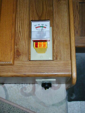 Added
a second duplex outlet for the line voltage meter and the polarity
monitor.
The receptacle is wired to one of the existing plugs (below the
cabinet)
and is fused with a 6 amp fuse. Now the voltage and polarity can
be easily monitored and the polarity can be checked after plugging in
the
house cord (by looking through the window) before ever getting
back
in the coach.
Added
a second duplex outlet for the line voltage meter and the polarity
monitor.
The receptacle is wired to one of the existing plugs (below the
cabinet)
and is fused with a 6 amp fuse. Now the voltage and polarity can
be easily monitored and the polarity can be checked after plugging in
the
house cord (by looking through the window) before ever getting
back
in the coach.
MODIFIED ENGINE AIR INLET
 The
inlet hose fell off the flange of the air intake box because it folded
in from the clamp pressure on the thin flange. I went to Home
Depot
and got a water drain like you would use in a flower bed. The
back
of it was just under 5 ¾ inches and JUST fit into the original
hose
flange on the air intake box. This makes it MUCH stronger.
While I had the box off the motorhome, I noticed that the hole through
the side of the motorhome didn’t even come close to lining up with the
air inlet in the box. I cut out about 1 inch more of the plastic
box to open up the air path. Previously, the filter minder would
jump almost to the top with a new filter. Now it reads
significantly
lower. Guess I was starving the engine for air all along.
Incidentally,
the hose connection to the engine air filter was reinforced the same
way
after it folded in on itself as well.
The
inlet hose fell off the flange of the air intake box because it folded
in from the clamp pressure on the thin flange. I went to Home
Depot
and got a water drain like you would use in a flower bed. The
back
of it was just under 5 ¾ inches and JUST fit into the original
hose
flange on the air intake box. This makes it MUCH stronger.
While I had the box off the motorhome, I noticed that the hole through
the side of the motorhome didn’t even come close to lining up with the
air inlet in the box. I cut out about 1 inch more of the plastic
box to open up the air path. Previously, the filter minder would
jump almost to the top with a new filter. Now it reads
significantly
lower. Guess I was starving the engine for air all along.
Incidentally,
the hose connection to the engine air filter was reinforced the same
way
after it folded in on itself as well.
REINFORCED STORAGE DOOR STRUT
MOUNTS
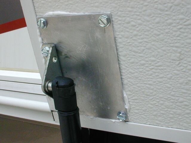 The
gas struts for the storage doors were originally mounted using long
screws
through the foot of the brace and into the door. The leverage was
such that all of the screws had loosened at one time or another and had
to continually be tightened. Several had actually pulled
completely
out over time. To address this problem, I made up some 3" X 4"
.062,
T6 aluminum plates. The corners were drilled to accept #10 X 3/4
sheet metal screws. I cleaned the surfaces well and then put
white
silicone caulk as a glue between the plate and the inside of the
door.
I screwed the plates to the door and then drilled the plate with the
appropriate
drill to accept the same screws and mounted the foot of the struts to
the
aluminum plates. The strut mounts are MUCH stronger now.
The
gas struts for the storage doors were originally mounted using long
screws
through the foot of the brace and into the door. The leverage was
such that all of the screws had loosened at one time or another and had
to continually be tightened. Several had actually pulled
completely
out over time. To address this problem, I made up some 3" X 4"
.062,
T6 aluminum plates. The corners were drilled to accept #10 X 3/4
sheet metal screws. I cleaned the surfaces well and then put
white
silicone caulk as a glue between the plate and the inside of the
door.
I screwed the plates to the door and then drilled the plate with the
appropriate
drill to accept the same screws and mounted the foot of the struts to
the
aluminum plates. The strut mounts are MUCH stronger now.
ADDED MINERAL OIL TO
BATTERIES
 I
had read about the oil that they sell to add to your batteries to stop
or minimize the corrosion around them. I did some research and it
seems that Edison used oil in his original batteries that were used
along
the railroads. In fact, they say you can still find the bottles
along
the tracks some places. Anyway, I did some research on the stuff
that is being sold today and found the patents for it. Turns out
that it is primarily mineral oil with a few other additives, primarily
for color. I made a call to a friend of mine who is a chemist to
see if there would be any reaction between sulfuric acid and mineral
oil.
He said that not only is mineral oil just fine in a battery, HE had
used
it for just that many years ago while working as a mechanic in his
Dad's
truck shop. He said that it worked great to stop the corrosion
and
outgassing so based on this information (and Edison's experience!) I
added
4 ounces of USP grade Mineral Oil (intestinal lubricant!) to each cell
in my 6 volt, deep cycle batteries. That amount seems to result
in
a blanket about 1/8 - 1/4 inch thick. If you take a cell cover
off
now while the batteries are charging, there are little tiny bubbles on
the top of the oil. No more big popping bubbles to carry sulfuric
acid out of the cells. We'll see how it works! I will
report
back in a few months.
I
had read about the oil that they sell to add to your batteries to stop
or minimize the corrosion around them. I did some research and it
seems that Edison used oil in his original batteries that were used
along
the railroads. In fact, they say you can still find the bottles
along
the tracks some places. Anyway, I did some research on the stuff
that is being sold today and found the patents for it. Turns out
that it is primarily mineral oil with a few other additives, primarily
for color. I made a call to a friend of mine who is a chemist to
see if there would be any reaction between sulfuric acid and mineral
oil.
He said that not only is mineral oil just fine in a battery, HE had
used
it for just that many years ago while working as a mechanic in his
Dad's
truck shop. He said that it worked great to stop the corrosion
and
outgassing so based on this information (and Edison's experience!) I
added
4 ounces of USP grade Mineral Oil (intestinal lubricant!) to each cell
in my 6 volt, deep cycle batteries. That amount seems to result
in
a blanket about 1/8 - 1/4 inch thick. If you take a cell cover
off
now while the batteries are charging, there are little tiny bubbles on
the top of the oil. No more big popping bubbles to carry sulfuric
acid out of the cells. We'll see how it works! I will
report
back in a few months.
April 2003 UPDATE:
It has now been over one year since I first added the mineral oil to
the batteries. I have had to add a very small amount of water one
time in that last year. I recently did a load test on the
batteries
and I cannot tell that there is any capacity loss at all in the last
year.
I don't believe that the addition of mineral oil has in any way harmed
the batteries and it has certainly eliminated the corrosion that was
occurring
on the terminals. I will definitely use the oil in any deep cycle
batteries I purchase in the future.
April 2004 UPDATE:
Its now been over two years since I added the oil to the first
set of batteries. I recently did another load test and I
can't tell that the batteries are degraded at all. When I added
the second set of batteries, (read about it here) it made it a bit
more difficult to accurately measure capacity on the first set but
overall, the battery bank is performing fine. I certainly have no
complaints relative to the addition of the oil to the cells.
Again, I have added water the the cells only once in the last year.
January 2007 UPDATE:
We were getting ready to be on the road for about 6 months and a lot of
that will be dry camping so I replaced all 4 of the coach batteries
with Interstate golf cart batteries from Sam's Club. I didn't
want to take a chance of having battery problems on the road and the
coach batteries are a BEAR to replace. The new batteries got 4
ounces of mineral oil in each cell before they were even
installed. Two of the batteries I replaced were 7 years old and
had the mineral oil in them for 5 years. The other two were about
4 years old and had the oil the whole time. When I removed the
old batteries there was ZERO corrosion anywhere including the battery
trays themselves. I am a big believer in the mineral oil in deep
cycle batteries.
INSTALLED SEDIMENT FILTER IN WATER
LINE FROM TANK
 Originally
there was not enough room to put an inlet filter directly on the inlet
to the water pump. I installed a filter in the line from the tank
to the pump. I got a regular filter designed to screw on the
inlet
of the pump and got the correct fitting to go on the ½ inch pipe
thread outlet of the filter to allow it to go in the ½ inch ID
hose
that runs from the tank to the pump. With the filter installed
that
way, I can separate the filter housing and immerse the pump side of the
filter in antifreeze solution to winterize the coach water system as
well.
Originally
there was not enough room to put an inlet filter directly on the inlet
to the water pump. I installed a filter in the line from the tank
to the pump. I got a regular filter designed to screw on the
inlet
of the pump and got the correct fitting to go on the ½ inch pipe
thread outlet of the filter to allow it to go in the ½ inch ID
hose
that runs from the tank to the pump. With the filter installed
that
way, I can separate the filter housing and immerse the pump side of the
filter in antifreeze solution to winterize the coach water system as
well.
INSTALLED POSITIVE AWNING LOCK
 On
the trip to the west coast, we got into a heck of a storm and the
awning
tried to open while going down the road. I replaced the A&E
awning
cam lock with a new one but I was not satisfied that would positively
prevent
the awning from opening under similar conditions. I developed a
positive
lock for the awning by using parts readily available from Home
Depot.
Later, I went back and replaced the end cap with a new one (from
MarksRV)
that contains a new pawl assembly so I now have a fully functional
A&E
lock as well as the TWO accessory locks. I don't think the awning
will be unintentionally coming open anymore.
On
the trip to the west coast, we got into a heck of a storm and the
awning
tried to open while going down the road. I replaced the A&E
awning
cam lock with a new one but I was not satisfied that would positively
prevent
the awning from opening under similar conditions. I developed a
positive
lock for the awning by using parts readily available from Home
Depot.
Later, I went back and replaced the end cap with a new one (from
MarksRV)
that contains a new pawl assembly so I now have a fully functional
A&E
lock as well as the TWO accessory locks. I don't think the awning
will be unintentionally coming open anymore.
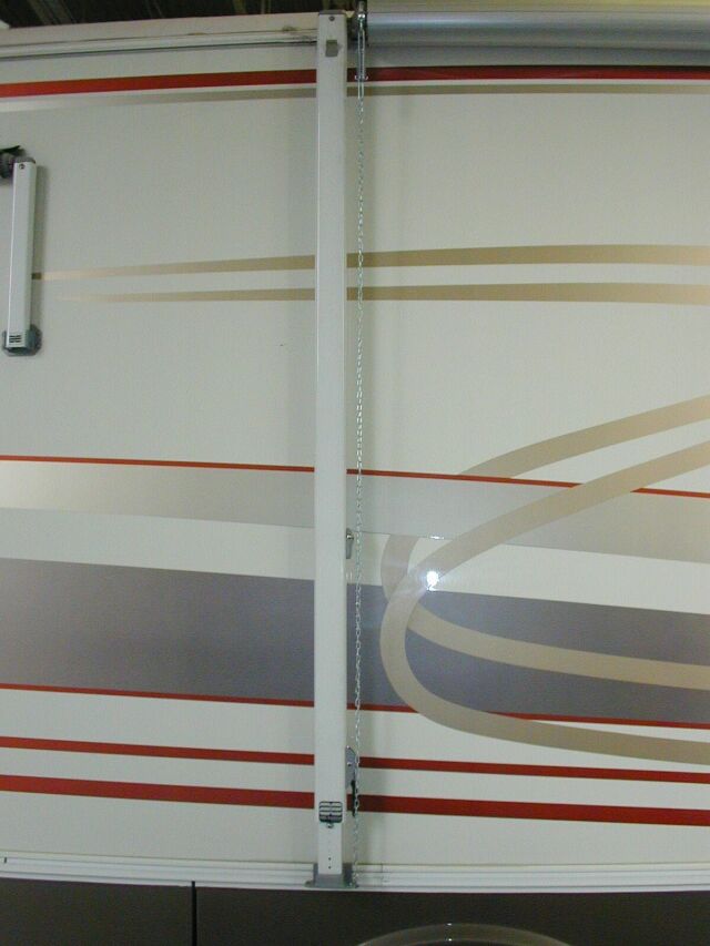
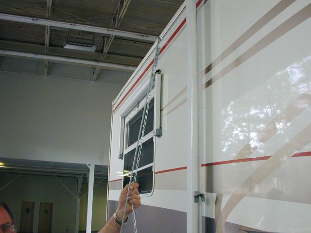
There are two things that prevent the A&E awning from unrolling while going down the highway. The primary thing is the locking pawl that is located in the right end cap of the awning. This consists of an aluminum disk and a pawl that engages it. The other thing that prevents the awning from unrolling is the tension on the springs located in both ends of the awning tube. Notice that the arms being locked against the rig have nothing to do with the awning staying rolled up. The awning WILL unroll with the arms still tight against the rig.
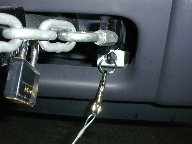
To address the unintentional unrolling, I used a heavy-duty picture hanger, a screen door catch spring, a stainless steel hose clamp, a couple of S hooks and 6 feet of chain for each end of the awning. Although it sounds a bit like a "Rube Goldburg" setup, the picture shows that it looks very neat and clean on the rig and performs very well. In addition, I have had several very positive comments on it. The picture hanger is clamped to the end cap on the awning using the stainless hose clamp and the door stop spring goes between the ring on the hanger and the foot of the upper brace for the awning. The whole lock can be installed or removed from the ground and it is impossible for the awning to open with it in place. The installation was very straightforward.

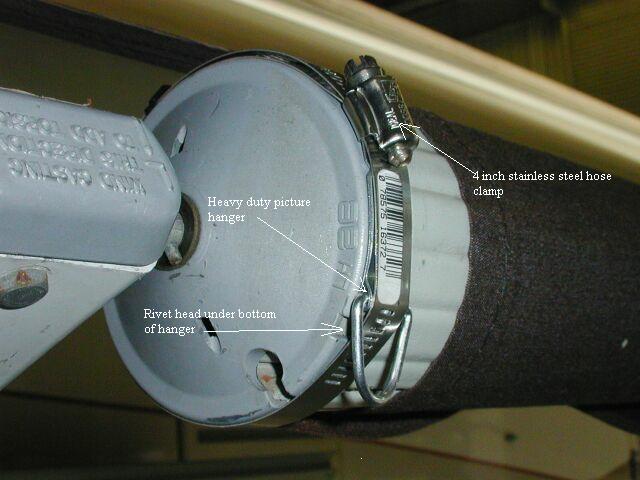 First,
mark the rivet that holds on the end cap that is on the outside when
the
awning is in the up and locked position. This is so you will know
where to install the picture hanger in the next step. Then open
the
awning and clamp the heavy duty picture hanger to the end cap using the
stainless steel clamp as shown in the second picture. The hanger
is placed with its bottom end just above the head of the outside rivet
that you marked earlier. This prevents it from slipping around
the
end cap when the spring pulls down on it. Tightening the
stainless
steel hose clamp forms the tab on the hanger around the curvature of
the
end cap. After the clamp is tightened, use a screwdriver and bend
the hanger away from the clamp enough to allow the S hook to go through
the opening.
First,
mark the rivet that holds on the end cap that is on the outside when
the
awning is in the up and locked position. This is so you will know
where to install the picture hanger in the next step. Then open
the
awning and clamp the heavy duty picture hanger to the end cap using the
stainless steel clamp as shown in the second picture. The hanger
is placed with its bottom end just above the head of the outside rivet
that you marked earlier. This prevents it from slipping around
the
end cap when the spring pulls down on it. Tightening the
stainless
steel hose clamp forms the tab on the hanger around the curvature of
the
end cap. After the clamp is tightened, use a screwdriver and bend
the hanger away from the clamp enough to allow the S hook to go through
the opening.
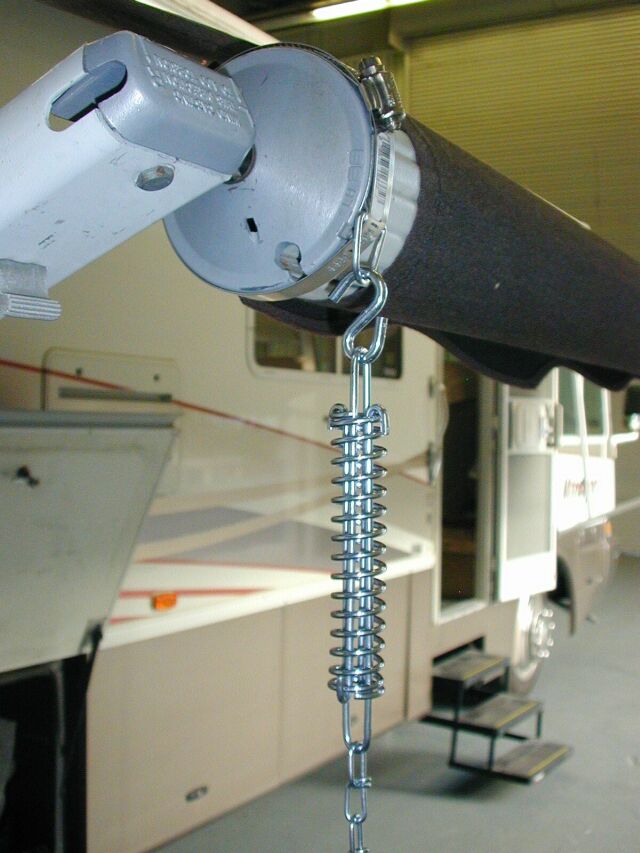
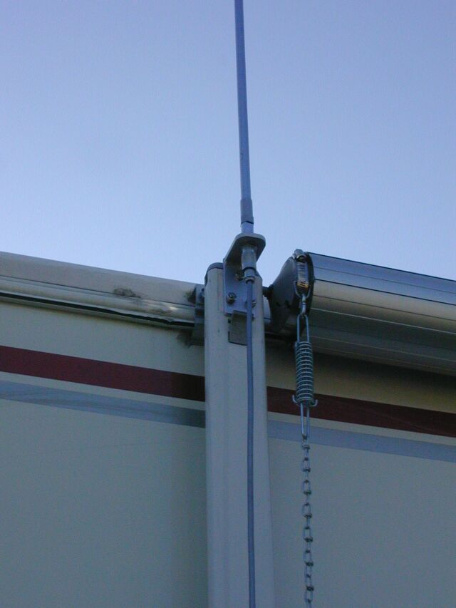
 This
is how the spring assembly hooks to the hanger. In the first
picture,
the awning is in the down position for clarity. The spring is
normally
removed and installed with the awning in the rolled up position.
As shown in the second picture, the spring is easily installed from the
ground by hooking the S hook over the top of the awning rod and holding
it in place on the rod by pulling down on the chain while you raise it
and hook it on the picture hanger.
This
is how the spring assembly hooks to the hanger. In the first
picture,
the awning is in the down position for clarity. The spring is
normally
removed and installed with the awning in the rolled up position.
As shown in the second picture, the spring is easily installed from the
ground by hooking the S hook over the top of the awning rod and holding
it in place on the rod by pulling down on the chain while you raise it
and hook it on the picture hanger.
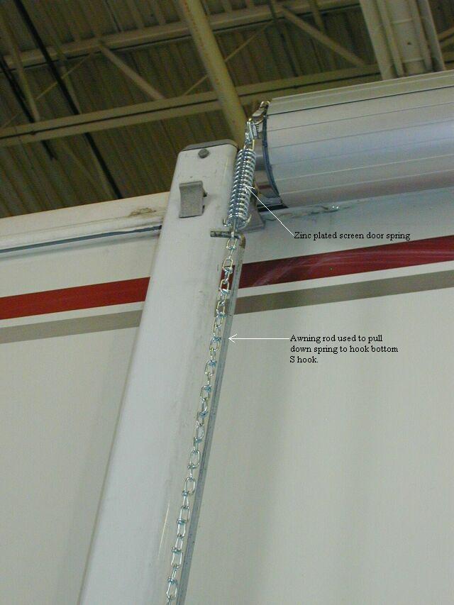
 To
hook the bottom S hook to the rafter foot, pull down on the spring with
the awning rod as shown in the first picture. I have found that
selecting
a chain length that results in pulling the spring so that is about half
compressed seems to very firmly lock the awning in the closed
position.
As a test, if you unlock the factory front travel lock and try to open
the awning now, the spring absorbs the shock and the awning will not
open.
I think the spring is a good idea to prevent undue strain on the system
in the event the front lock fails. This is really a very simple
modification
to perform and the total price is around $15.00!
To
hook the bottom S hook to the rafter foot, pull down on the spring with
the awning rod as shown in the first picture. I have found that
selecting
a chain length that results in pulling the spring so that is about half
compressed seems to very firmly lock the awning in the closed
position.
As a test, if you unlock the factory front travel lock and try to open
the awning now, the spring absorbs the shock and the awning will not
open.
I think the spring is a good idea to prevent undue strain on the system
in the event the front lock fails. This is really a very simple
modification
to perform and the total price is around $15.00!
UPDATE: I later added clear vinyl tubing over the chains to prevent marring of the arms from the chain vibrating in the wind while going down the highway.
INSTALLED AIR FILTER FOR DASH AIR
CONDITIONER
 While
in Wal-Mart, I spotted some air filters designed to go in floor vents
to
prevent junk from falling into the openings. It turned out they
were
the perfect size to cover the air intake on the dash AC. This
will
prevent cat or dog hair from getting into the evaporator. The
filter
is just tucked in front of the opening and the airflow holds it up
against
the opening. It doesn't seem to have a significant effect on air
flow so we will see how it works out long-term.
While
in Wal-Mart, I spotted some air filters designed to go in floor vents
to
prevent junk from falling into the openings. It turned out they
were
the perfect size to cover the air intake on the dash AC. This
will
prevent cat or dog hair from getting into the evaporator. The
filter
is just tucked in front of the opening and the airflow holds it up
against
the opening. It doesn't seem to have a significant effect on air
flow so we will see how it works out long-term.
INSTALLED NEW SHOWER DOOR SWEEP
 The
old sweep had failed and Damon could no longer get them, Seems
the
supplier that made my shower door had gone out of business. I
went
to the hardware store and got a standard vinyl shower door sweep and
cut
off half of the top ridge so it would slide in the groove that the end
screw goes into. The dimensions came out perfectly and the door
is
once again sealed. The picture shows the top ridge trimmed to fit
the slot.
The
old sweep had failed and Damon could no longer get them, Seems
the
supplier that made my shower door had gone out of business. I
went
to the hardware store and got a standard vinyl shower door sweep and
cut
off half of the top ridge so it would slide in the groove that the end
screw goes into. The dimensions came out perfectly and the door
is
once again sealed. The picture shows the top ridge trimmed to fit
the slot.
INSTALLED WARNING LIGHT & SWITCH
FOR
BRAKE BUDDY

 I
wanted to be able to activate and monitor the Brake Buddy in the Toad
from
the driver’s seat of the motorhome. I ran two wires in the wire
chase
on the driver’s side of the coach from the back of the coach to the
dash
of the motorhome. I then installed a four
wire flat connector on a harness from the motorhome to connect to a
matching connector on the Liberty. I used two of the wires on the
connector for the ground connection and used one wire for the brake
light
indication and one for activation of the Brake Buddy remotely.
The
brake indication wire goes to a red
indicator lamp installed in the dash of the motorhome just above
the
switch bank. The other end of this wire is connected directly to
the brake lamp switch in the Jeep. The other wire in the harness
is connected to the “hot” wire in the harness that connects from the brake-away
switch on the Jeep to the Brake Buddy. It connects to a push
button mounted on the front face of the transmission console in the
motorhome. Now, when I press the button, the Brake Buddy is
activated
and the lamp on the dash comes on. When the Brake Buddy activates
itself the lamp comes on as well.
I
wanted to be able to activate and monitor the Brake Buddy in the Toad
from
the driver’s seat of the motorhome. I ran two wires in the wire
chase
on the driver’s side of the coach from the back of the coach to the
dash
of the motorhome. I then installed a four
wire flat connector on a harness from the motorhome to connect to a
matching connector on the Liberty. I used two of the wires on the
connector for the ground connection and used one wire for the brake
light
indication and one for activation of the Brake Buddy remotely.
The
brake indication wire goes to a red
indicator lamp installed in the dash of the motorhome just above
the
switch bank. The other end of this wire is connected directly to
the brake lamp switch in the Jeep. The other wire in the harness
is connected to the “hot” wire in the harness that connects from the brake-away
switch on the Jeep to the Brake Buddy. It connects to a push
button mounted on the front face of the transmission console in the
motorhome. Now, when I press the button, the Brake Buddy is
activated
and the lamp on the dash comes on. When the Brake Buddy activates
itself the lamp comes on as well.
Note that the warning lamp is connected to the brake switch in the Liberty, NOT to the Brake Buddy itself. Not only is that simpler but should the Brake Buddy fail to completely release the brakes (which has NEVER happened), I will see the indication and stop long before any damage to the brakes can occur.
INSTALLED MOUNT FOR AMATEUR RADIO HF
ANTENNA
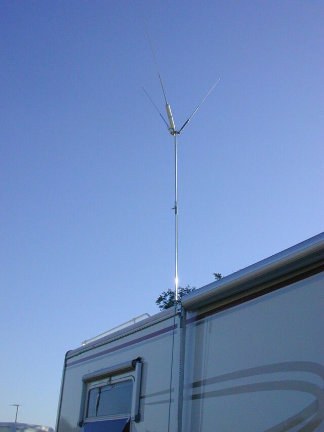 I
made a mount for my amateur HF antenna out of 1.5 inch wide by 1/4 inch
thick 6061-T6 aluminum. The mount is bolted to the rear awning
support
rafter. In this manner, it can be used with the awning against
the
coach or with the awning out and the arm staked down against the
ground.
I use a Hustler bumper mount antenna with the Hustler Spider to allow
the
use of three resonators so three bands can be used without taking down
the antennas. To hook it up, I mount the Hustler and then run a
piece
of RG-8X to the front of the coach where it connects to a similar piece
of coax that runs through a feedthru into the coach.
I
made a mount for my amateur HF antenna out of 1.5 inch wide by 1/4 inch
thick 6061-T6 aluminum. The mount is bolted to the rear awning
support
rafter. In this manner, it can be used with the awning against
the
coach or with the awning out and the arm staked down against the
ground.
I use a Hustler bumper mount antenna with the Hustler Spider to allow
the
use of three resonators so three bands can be used without taking down
the antennas. To hook it up, I mount the Hustler and then run a
piece
of RG-8X to the front of the coach where it connects to a similar piece
of coax that runs through a feedthru into the coach.
I have checked the SWR with this rig and it is typically very close to 1:1 at resonance and under 1.6:1 at the band edges. The antenna seems to play very well and I am back on HF when we are camped.
ADDED SECOND SET OF GOLF CART
BATTERIES
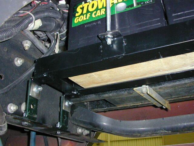 I
added a second set of golf cart batteries to the coach by building a
battery
box out of 1/8 inch thick, 2 inch angle steel. The box is bolted
to the frame, using heavy steel brackets, behind the original pair of
batteries
and the batteries are wired in parallel with the original set to
deliver
440 amp hours of capacity. The addition is very nice when we dry
camp. I used the mineral oil blanket in these batteries as
well.
To install the new box, I placed it on a floor jack and jacked it up
into
place. This worked very well considering the batteries weigh
about
62 pounds each. Yes, I have heard the the old story that you
shouldn't
mix old and new batteries but in my experience, as long as they are the
same chemistry, there is no problem with it. I have done it
several
times before and it has worked just fine. In this case, the
original
batteries were installed in 2000 so they are three years old. The
new ones and the old play very happily together so I am happy with the
setup.
I
added a second set of golf cart batteries to the coach by building a
battery
box out of 1/8 inch thick, 2 inch angle steel. The box is bolted
to the frame, using heavy steel brackets, behind the original pair of
batteries
and the batteries are wired in parallel with the original set to
deliver
440 amp hours of capacity. The addition is very nice when we dry
camp. I used the mineral oil blanket in these batteries as
well.
To install the new box, I placed it on a floor jack and jacked it up
into
place. This worked very well considering the batteries weigh
about
62 pounds each. Yes, I have heard the the old story that you
shouldn't
mix old and new batteries but in my experience, as long as they are the
same chemistry, there is no problem with it. I have done it
several
times before and it has worked just fine. In this case, the
original
batteries were installed in 2000 so they are three years old. The
new ones and the old play very happily together so I am happy with the
setup.
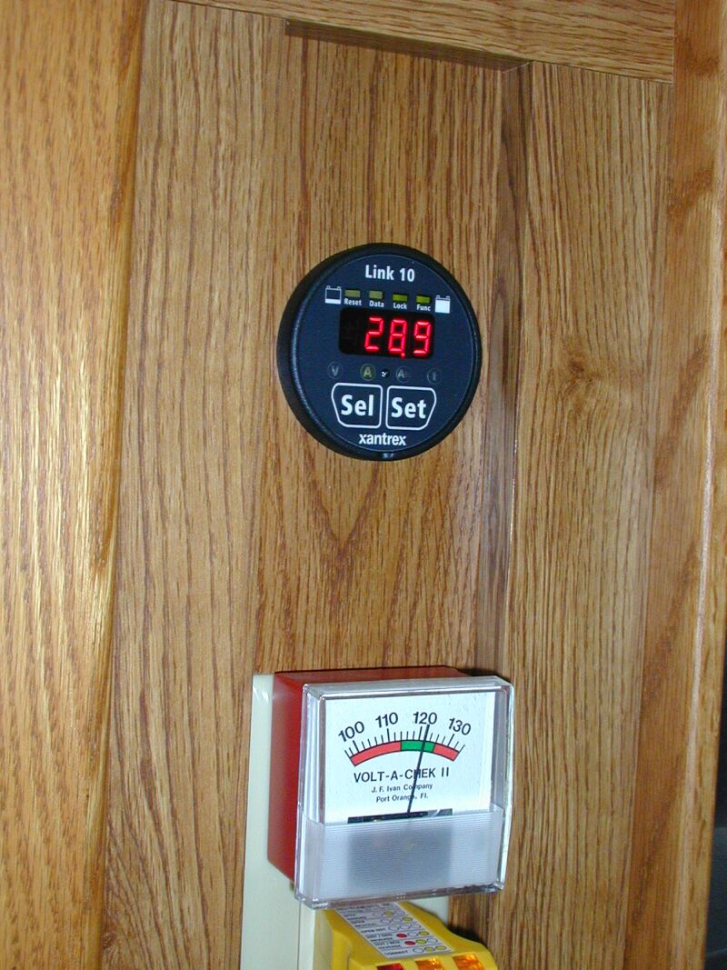
ADDED LINK 10 BATTERY MONITOR
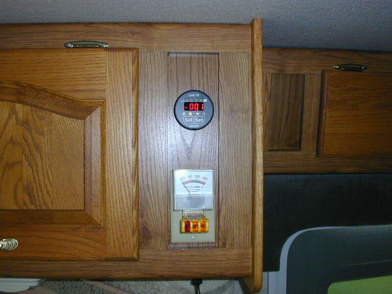 I
installed a Link 10 battery monitor in the panel above the previously
installed
AC circuit voltage and polarity monitor. The Link 10 uses a 500
amp
shunt installed in the negative lead of the battery for all the current
measurements. I ran four conductor, 16 gauge twisted cable
(speaker
wiring) for the connections to the batteries and the shunt. I
made
a new battery ground cable and interconnecting cable from #1 welding
cable
and soldered on the appropriate copper terminals. In the first
picture,
you can see the quiescent power consumption of the coach. Not
bad!
I
installed a Link 10 battery monitor in the panel above the previously
installed
AC circuit voltage and polarity monitor. The Link 10 uses a 500
amp
shunt installed in the negative lead of the battery for all the current
measurements. I ran four conductor, 16 gauge twisted cable
(speaker
wiring) for the connections to the batteries and the shunt. I
made
a new battery ground cable and interconnecting cable from #1 welding
cable
and soldered on the appropriate copper terminals. In the first
picture,
you can see the quiescent power consumption of the coach. Not
bad!

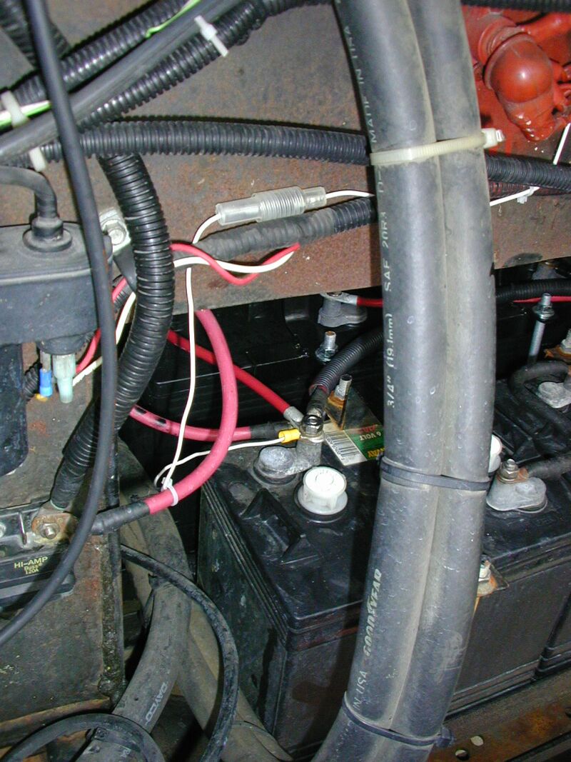
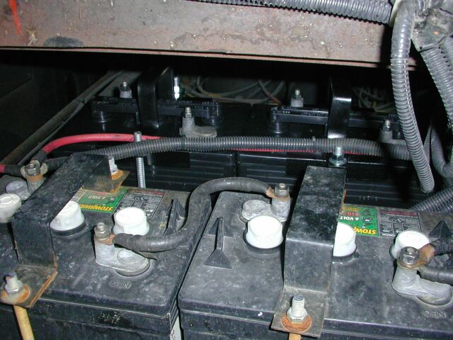
 Here's
a shot of the shunt and its wiring and the voltage sense lead that is
fused
and connects directly to the battery positive terminal. The third
picture is the back of the meter and how the wiring was run in the
cabinet.
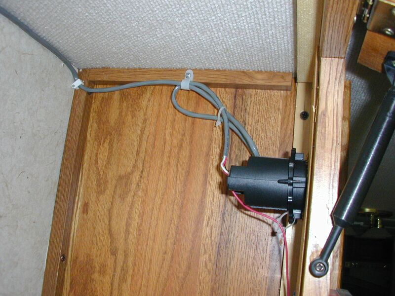
Here's
a shot of the shunt and its wiring and the voltage sense lead that is
fused
and connects directly to the battery positive terminal. The third
picture is the back of the meter and how the wiring was run in the
cabinet.
The Link 10 meter has two DC voltage inputs. One is the line going to the battery for voltage measurement and the other is the supply that runs the meter itself. This second supply is not a precision source and draws about 50 milliamperes when the meter is on. I connected this line to the power line for the 12 volt lamp located in the cabinet below the meter. In this manner, when the master switch for the house batteries is off, the meter draws essentially nothing from the batteries. The only disadvantage of this is that you have to reset the meter when you power up the coach but all the settings like battery amp hours and charge efficiency are retained. This system really works very well for keeping track of the batteries while dry camping.

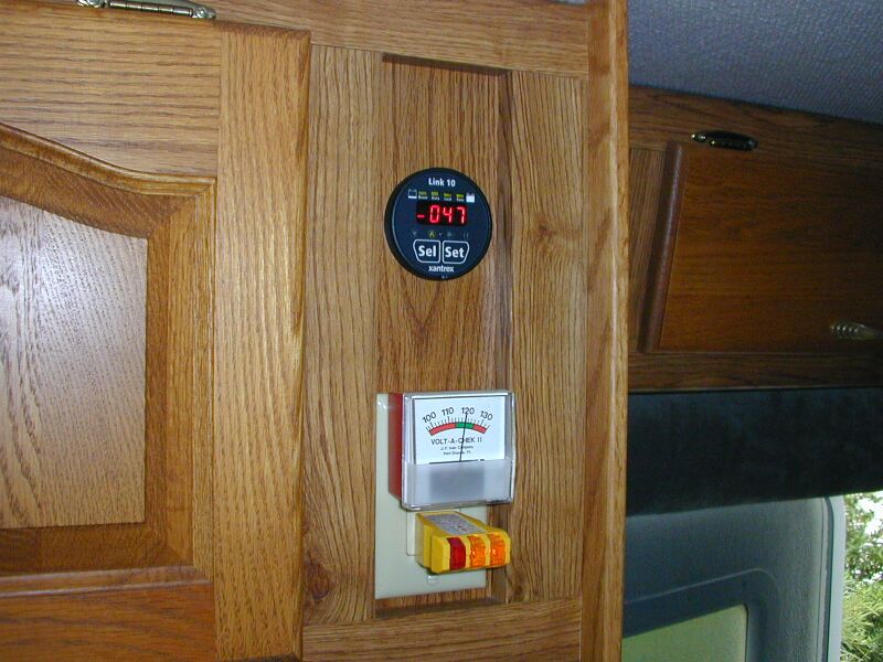 These
pictures show some current data that I found interesting. The
first
is the current from the Magnetek converter after I had been plugged in
for a while. It started out putting over 40 amps into the
batteries
and here, had dropped to about 29 amps. The batteries were down
about
10% at this time. The second shot is with the coach back on
battery
power and shows the current drawn by the inverter to run the
refrigerator
on electricity. The last shot shows the current drawn to run a
small
"Snark" vacuum cleaner on 110 VAC.
These
pictures show some current data that I found interesting. The
first
is the current from the Magnetek converter after I had been plugged in
for a while. It started out putting over 40 amps into the
batteries
and here, had dropped to about 29 amps. The batteries were down
about
10% at this time. The second shot is with the coach back on
battery
power and shows the current drawn by the inverter to run the
refrigerator
on electricity. The last shot shows the current drawn to run a
small
"Snark" vacuum cleaner on 110 VAC.
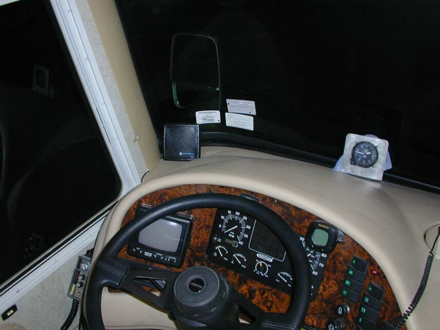
INSTALLED ICOM IC-208H AMATEUR RADIO


 The
old Azden
I had in Princess had become somewhat unreliable and it didn't
have tone capability so it was time to get something new. I
looked for a long time and finally decided on the dual band Icom
IC-208H.
It is a neat little rig that puts out 55 watts on VHF and 50 on UHF and
of course, has full tone capability. The installation was easy
since the antenna I had originally installed was a dual band
antenna. I checked the SWR and it was under 2:1 on both
bands. I installed the control head on the dash and the
transmitter portion on the side of the console under the dash.
This made it easy to get to power (this thing needs a 20 amp circuit!)
and the antenna. Since it comes with the separation cable, it was
a relatively easy installation. For a speaker, I used a Motorola
communications speaker I picked up at the TRW swapmeet a while
back. I think we are all set for VHF and UHF now.
The
old Azden
I had in Princess had become somewhat unreliable and it didn't
have tone capability so it was time to get something new. I
looked for a long time and finally decided on the dual band Icom
IC-208H.
It is a neat little rig that puts out 55 watts on VHF and 50 on UHF and
of course, has full tone capability. The installation was easy
since the antenna I had originally installed was a dual band
antenna. I checked the SWR and it was under 2:1 on both
bands. I installed the control head on the dash and the
transmitter portion on the side of the console under the dash.
This made it easy to get to power (this thing needs a 20 amp circuit!)
and the antenna. Since it comes with the separation cable, it was
a relatively easy installation. For a speaker, I used a Motorola
communications speaker I picked up at the TRW swapmeet a while
back. I think we are all set for VHF and UHF now.
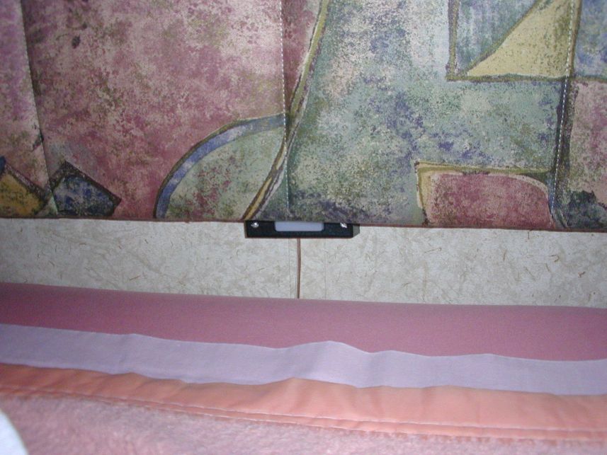
ADDED REMOTE SWITCH FOR INVERTER
 The
furnace control switch mentioned above worked so well that I wanted to
install a similar switch to control the inverter when we dry
camp. The inverter draws about 1.5 amps when on because it is
running the "instant start" feature in the TV's as well as other 110
volt parasitic loads. That's a lot of power consumption if
allowed to run all night. To address this, I ran a 24 gauge wire
pair through the wire chaise into the bedroom and
mounted a switch just below the headboard of the bed to control the
inverter. The wires are connected in parallel with the front
inverter control switch. Now the inverter can be turned on or off
from the bedroom. Nice for watching TV when we dry camp.
The
furnace control switch mentioned above worked so well that I wanted to
install a similar switch to control the inverter when we dry
camp. The inverter draws about 1.5 amps when on because it is
running the "instant start" feature in the TV's as well as other 110
volt parasitic loads. That's a lot of power consumption if
allowed to run all night. To address this, I ran a 24 gauge wire
pair through the wire chaise into the bedroom and
mounted a switch just below the headboard of the bed to control the
inverter. The wires are connected in parallel with the front
inverter control switch. Now the inverter can be turned on or off
from the bedroom. Nice for watching TV when we dry camp.
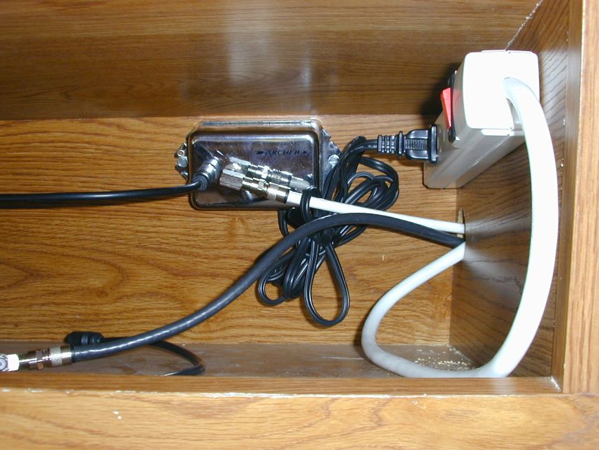
INSTALLED
SATELLITE WIRING

 I
had DirecTV installed at the house and it was time to wire Princess so
we could use it on the road. I ran RG-6 cable from the cabinet
over the driver's position, across and down the right inside window
trim, across the firewall and out to the coach battery area. I
Installed a bracket there for connection to the cable to the
dish. I also installed another RG-6 cable (the white one) over to
the audio/video switch box in the DVD/VCR cabinet. In addition, I
cleaned up all the wiring for the audio/video switch center that was
just sitting on top of the DVD/VCR. I removed the lid of the
DVD/VCR and drilled holes so the switch box would be permanently
mounted in place. It appears that the chassis of the satellite
receiver is not isolated from ground so I could get a "tingle" off the
box so I ran a three wire extension cord across and into the
compartment for the satellite receiver which took care of the grounding
problem. I made up a PVC mount for my second satellite dish,
complete with 4 inch levelers, to assure easy alignment of the dish in
the campsite. The switch box now allows selection of satellite,
antenna or DVD/VCR for either TV as well as allowing the DVD/VCR to
record either the satellite or antenna. Now, when we travel, we
can use a receiver from the home, and have satellite TV on the road.
I
had DirecTV installed at the house and it was time to wire Princess so
we could use it on the road. I ran RG-6 cable from the cabinet
over the driver's position, across and down the right inside window
trim, across the firewall and out to the coach battery area. I
Installed a bracket there for connection to the cable to the
dish. I also installed another RG-6 cable (the white one) over to
the audio/video switch box in the DVD/VCR cabinet. In addition, I
cleaned up all the wiring for the audio/video switch center that was
just sitting on top of the DVD/VCR. I removed the lid of the
DVD/VCR and drilled holes so the switch box would be permanently
mounted in place. It appears that the chassis of the satellite
receiver is not isolated from ground so I could get a "tingle" off the
box so I ran a three wire extension cord across and into the
compartment for the satellite receiver which took care of the grounding
problem. I made up a PVC mount for my second satellite dish,
complete with 4 inch levelers, to assure easy alignment of the dish in
the campsite. The switch box now allows selection of satellite,
antenna or DVD/VCR for either TV as well as allowing the DVD/VCR to
record either the satellite or antenna. Now, when we travel, we
can use a receiver from the home, and have satellite TV on the road.
Interesting note; the satellite receiver draws almost the same amount
of power whether it is turned on or off. If running it on an
inverter, it would be a good idea to unplug it when not being used to
minimize the battery drain.
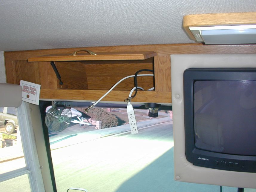
INSTALLED LINE
AMPLIFIER FOR SATELLITE TV
 The signal from the satellite receiver had a lot of
noise (snow in the picture) when the receiver was used in the
motorhome. It was fine at home
so I suspected it was due to signal loss through the signal switch in
the motorhome. I picked up a TV R.F. amplifier at the TRW Swap
Meet and installed it between the receiver and the switch.
This DRAMATICALLY improved the picture. It is crystal clear now
on both front and back TV.
The signal from the satellite receiver had a lot of
noise (snow in the picture) when the receiver was used in the
motorhome. It was fine at home
so I suspected it was due to signal loss through the signal switch in
the motorhome. I picked up a TV R.F. amplifier at the TRW Swap
Meet and installed it between the receiver and the switch.
This DRAMATICALLY improved the picture. It is crystal clear now
on both front and back TV.
INSTALLED OLYMPIAN
WAVE 6 CATALYTIC HEATER
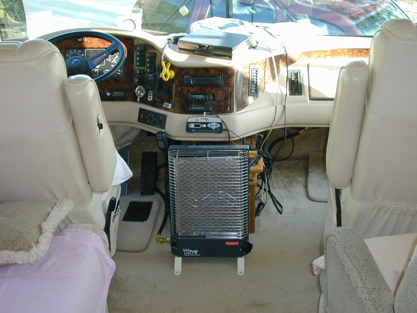 We
really enjoy dry camping in cooler weather and at least here in
California, even in the summer,
camping in the mountains (our favorite) can get pretty chilly in the
evening. I had done quite a bit of reading about the
catalytic heaters and there are certainly two sides to the
discussion. There are those that say they are very dangerous
because of carbon
monoxide and those that say they are perfectly safe if you use them
correctly. Since we never sleep with any kind of heater on, I
decided it was a safe thing to do so here's how I installed the
Olympian Wave 6 in Princess.
We
really enjoy dry camping in cooler weather and at least here in
California, even in the summer,
camping in the mountains (our favorite) can get pretty chilly in the
evening. I had done quite a bit of reading about the
catalytic heaters and there are certainly two sides to the
discussion. There are those that say they are very dangerous
because of carbon
monoxide and those that say they are perfectly safe if you use them
correctly. Since we never sleep with any kind of heater on, I
decided it was a safe thing to do so here's how I installed the
Olympian Wave 6 in Princess.
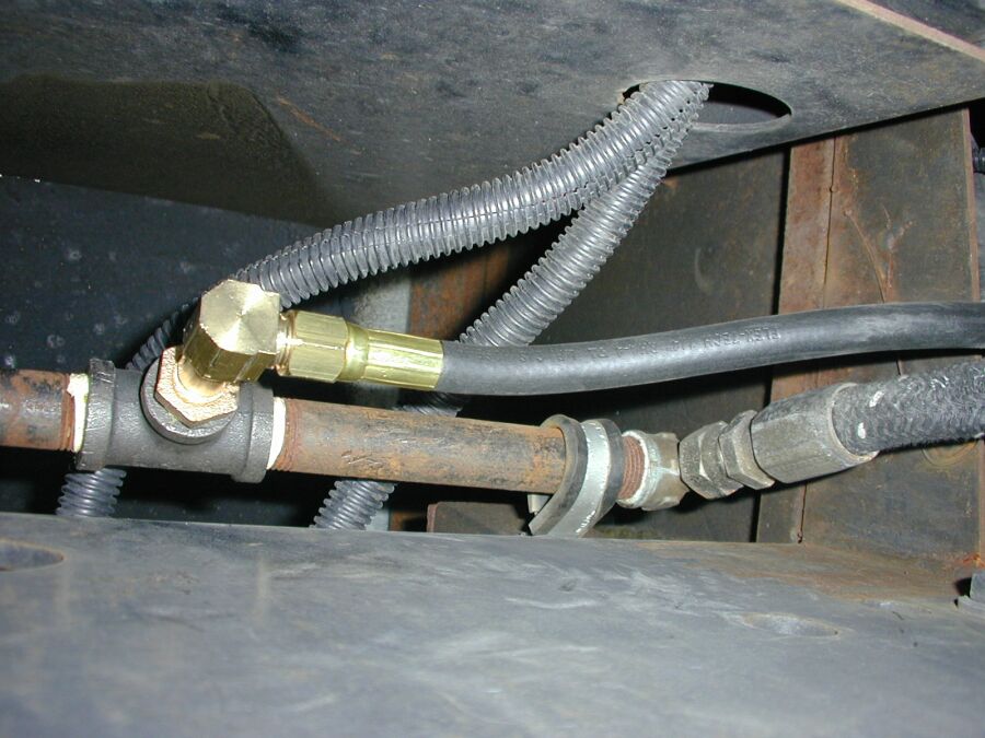
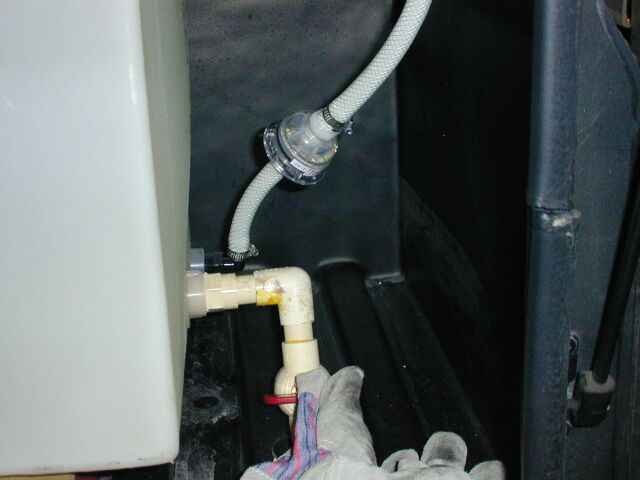
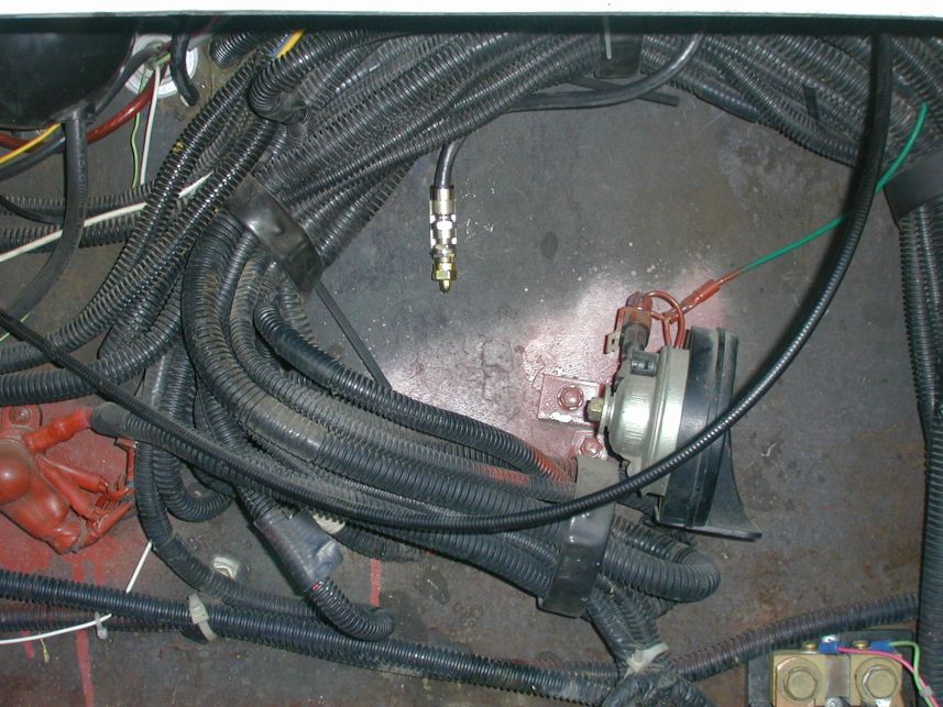
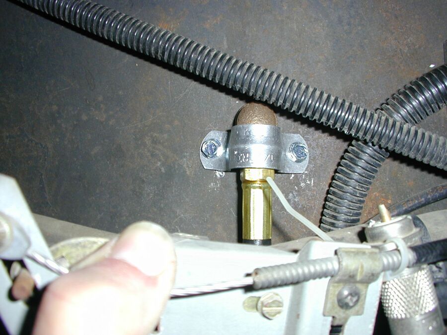 The biggest challenge was to get the low pressure
propane to the heater. Our
Onan generator is run on low pressure propane vapor so there was a 1/2
inch black
iron pipe right under the right front of the motorhome to deliver fuel
to the generator. As it turns out, there was a coupling in the
pipe, just behind the connection for the generator. I removed the
coupling and put in a black iron "T". The side port of the "T"
was reduced
down to 1/4 inch pipe thread and a 5 foot hose was connected there and
run up to the front of the firewall. Then I drilled a hole
through the firewall
and put through a 1/4 inch brass pipe nipple and connected the hose to
it
through a street "L" and used a 1/2 inch pipe clamp to secure it to the
firewall.
The biggest challenge was to get the low pressure
propane to the heater. Our
Onan generator is run on low pressure propane vapor so there was a 1/2
inch black
iron pipe right under the right front of the motorhome to deliver fuel
to the generator. As it turns out, there was a coupling in the
pipe, just behind the connection for the generator. I removed the
coupling and put in a black iron "T". The side port of the "T"
was reduced
down to 1/4 inch pipe thread and a 5 foot hose was connected there and
run up to the front of the firewall. Then I drilled a hole
through the firewall
and put through a 1/4 inch brass pipe nipple and connected the hose to
it
through a street "L" and used a 1/2 inch pipe clamp to secure it to the
firewall.
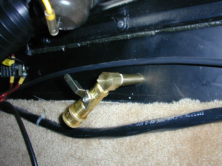 Inside
the motorhome, I used a quick disconnect that came with a shut-off
valve (Mr. Heater P/N F276181) that I picked up at Camping World.
By using this, I could disconnect the heater when we were not using
it. I
connected the heater to the quick disconnect with a piece of welding
hose I had a welding shop make up. All in all it makes for a very
nice installation and the heater works VERY well. I would HIGHLY
recommend one of these heaters if you remember the required safety
precautions. It is very important to remember that these heaters
consume oxygen so you MUST have a
couple of windows cracked to supply make-up air!!
Inside
the motorhome, I used a quick disconnect that came with a shut-off
valve (Mr. Heater P/N F276181) that I picked up at Camping World.
By using this, I could disconnect the heater when we were not using
it. I
connected the heater to the quick disconnect with a piece of welding
hose I had a welding shop make up. All in all it makes for a very
nice installation and the heater works VERY well. I would HIGHLY
recommend one of these heaters if you remember the required safety
precautions. It is very important to remember that these heaters
consume oxygen so you MUST have a
couple of windows cracked to supply make-up air!!
INSTALLED FAN INSIDE NORCOLD REFRIGERATOR
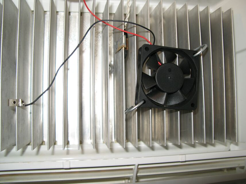 I have used 12 volt computer fans inside the box of
my RV
refrigerators before and it really helped make the cooling more even
throughout
the box. Normally, I have wired the fan
ACROSS (that’s correct, across) the door switch. For
those that are not familiar with this
wiring, the reason it works is that the current drawn by the fan is
MUCH less
than the current required to light the lamp.
Therefore, with the fan across the switch, when the door is
closed, the
fan is effectively in series with the lamp and runs.
When the door opens, the switch shorts out
the fan, connecting one side of the lamp to ground and the lamp lights. The main reason I did it this way is so that
with the door open, I’m not stirring up the cold air and mixing it with
warm
air from the room.
I have used 12 volt computer fans inside the box of
my RV
refrigerators before and it really helped make the cooling more even
throughout
the box. Normally, I have wired the fan
ACROSS (that’s correct, across) the door switch. For
those that are not familiar with this
wiring, the reason it works is that the current drawn by the fan is
MUCH less
than the current required to light the lamp.
Therefore, with the fan across the switch, when the door is
closed, the
fan is effectively in series with the lamp and runs.
When the door opens, the switch shorts out
the fan, connecting one side of the lamp to ground and the lamp lights. The main reason I did it this way is so that
with the door open, I’m not stirring up the cold air and mixing it with
warm
air from the room.
I wanted to install one in my Norcold 982IM but the door
switch was not readily accessible. In
looking at the schematic of the control board, I noticed that the fan
control
is a negative terminal. That got me to
wondering if the lamp is at 12 volts all the time and the control board
grounds
one end of the lamp in response to the door switch.
I pulled the cover off the lamp and sure enough,
that’s how
it works. I was able to wire the
positive terminal of the fan to the innermost terminal on the lamp and
the
ground was picked up on the cooling fins.
The fan is mounted to the fins with a pair of hitch pin clips
from Lowe's. The ground wire is connected to the fins with a
spring clip. Now with the door open the fan is off and with the
door closed, it
runs. If someone wanted the fan on all
the time, just use the outermost lamp terminal.
It’s at +12 all the time.
The only fly in the ointment is that the +12 is
supplied to
the lamp at all times… even with the box turned off.
I decided this wasn’t a problem for me since
if I have power on in the coach, I am typically using the refrigerator. If this was a problem, a tiny toggle switch
could be installed near the fan to turn it off when desired.
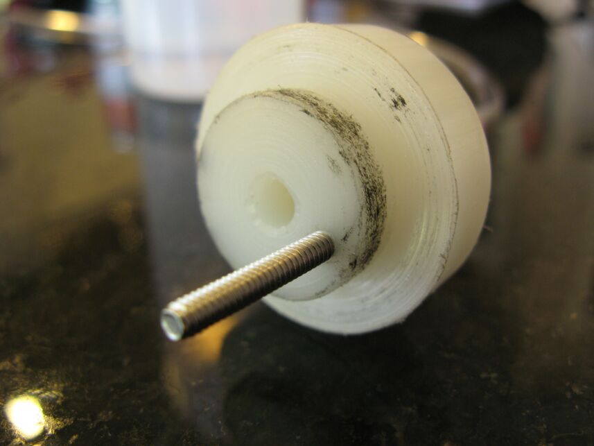
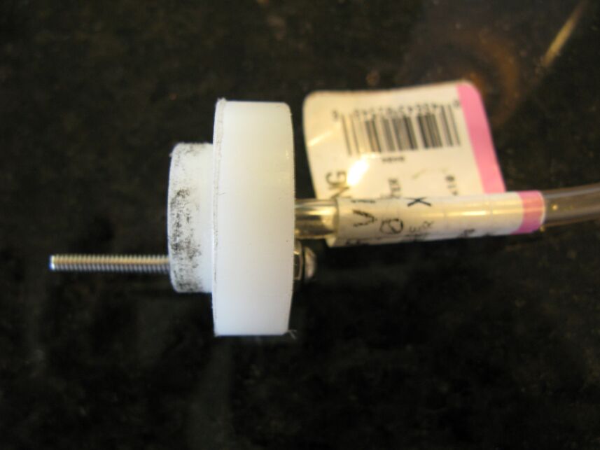
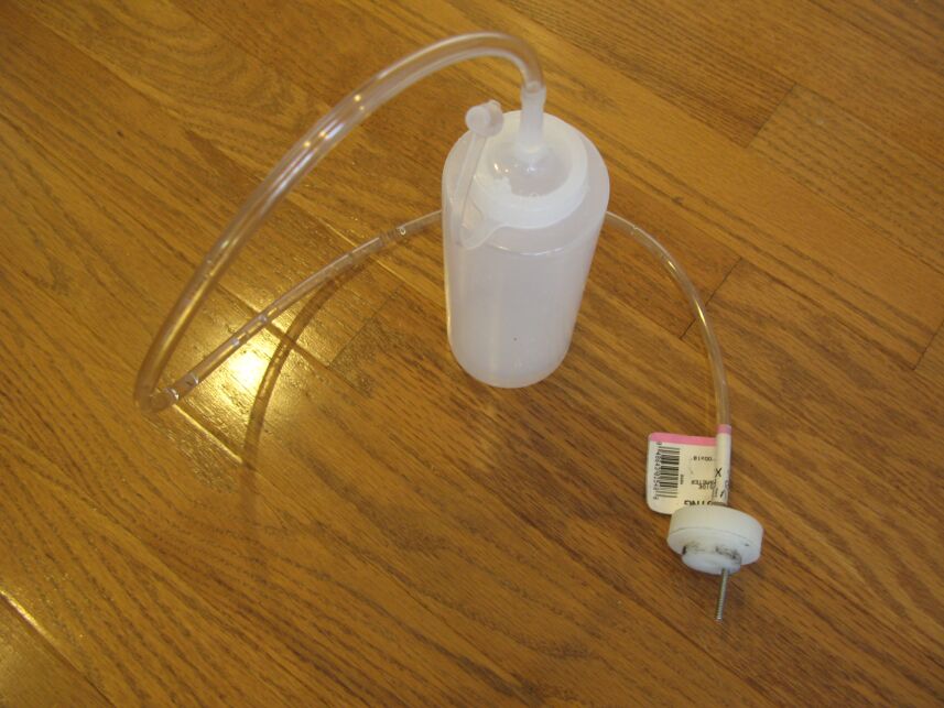
I machined the body (the part that goes into the battery fill port) so
it is a snug
fit. That way it holds itself in place while you fill it.
The hole through the center is just under 1/4 inch so the tubing is a
press fit into it. The squeeze bottle came from Wally World and
is a press fit into the tubing. The screw is a stainless 6-32
that is set at 1.125 inches below the flange. That sets the water
level at 1/8 inch below the split ring... just the way they want it.
To use the tool, I connect a voltmeter between the stainless screw and
ground. Fill the bottle with distilled water and turn the bottle
upside down and gently squeeze to dispense the water into the
cell. That way, as soon as the meter shows a voltage, you know
the acid is touching the screw and is at the correct level. Of
course the voltage is dependent on the cell
you are in since you are actually measuring from that cell to ground
but it is a VERY definite rise once the acid hits the screw. It
took me about 5 minutes to fill all the cells in my four batteries
using this tool and I KNOW they are at the correct level.
My WebCounter says you
are
visitor number
since August 30, 2002.
Get your free web page hit counter at ![]()
E-mail me at ultrasport(REMOVE)@mail.com
© Copyright 2002-7 Steve Das
More to follow.... I'm sure!